


VFD-F Series
DELTA ELECTRONICS, INC. ALL RIGHTS RESERVED
5-22
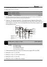
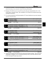
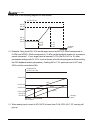
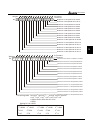
Please refer to the following diagram for more details:
04-12
04-16
04-11
04-15
04-19
04-09
04-13
04-17
04-10
04-14
04-18
01-00, 10-10
Analog
input
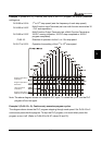
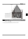
Example: Using the AVI(0~10V) as the target source and ACI1(4~20mA corresponds to
0~5Pa) and ACI2(0~10mA corresponds to 0~4Pa) as the feedback location for a pressure
sensor connected. If your target value is between 3~7Pa (Set Pr.10-01 to 10, other
parameters settings refer Pr.10-01 to set as shown in the following diagram and then setting
the PID feedback relative parameters.) If setting AVI to 7.5V, pressure sum of ACI1 and
ACI2 could be controlled at 6Pa.
Pressure Pa
Analog
input
10-10=10.0 Pa
04-12=70
AVI
ACI2
ACI1
04-16=50
04-20=40
04-11=30
04-15=0
04-19=0
04-9=0V
04-17=0mA
04-13=4mA
04-18=10mA
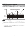
When analog input current of ACI1/ACI2 is lower than Pr.04-13/Pr.04-17, EF warning will
pup-up.