


5
VFD-F Series
DELTA ELECTRONICS, INC. ALL RIGHTS RESERVED
5-7
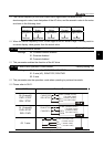
01 - 19 JOG Frequency
a
Factory Setting: 6.00
Settings 0.0 Hz~120.00 Hz Unit: 0.1sec
When the JOG function is to be utilized, users need to use the multi-function input terminals
(Pr. 04-00 to 04-07 set to 07) or the JOG key on keypad. Once a JOG command is initiated,
the AC drive will accelerate from the Minimum Output Frequency (Pr.01-05) to the JOG
frequency (Pr.01-19).
The accel/decel time of the JOG operation is determined by the JOG accel/decel speed
(Pr.01-17 and 01-18).
When the drive is in operation, the JOG command is disabled.
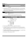
01 - 20 S Curve Delay Time in Accel Factory Setting: 0.00
01 - 21 S Curve Delay Time in Decel
Settings 0.00~2.50sec
These parameters enable the S curve. The longer the S curve time period the smoother the
transition between speeds.
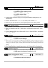
01 - 22 Modulation Index
a
Factory Setting: 1.00
Settings 0.90~1.20 Unit: 0.1
This parameter sets the ratio of the Maximum Output Voltage to the input voltage.
The Maximum Output Voltage (Pr.01-02) is normally limited to the input voltage. With the
Modulation Index parameter, the user is able to increase the output voltage beyond the
incoming line voltage.
A Modulation Index of 1, defines the Maximum Output Voltage (Pr. 1-02) is equal to the
input voltage.
A Modulation index of 1.2, defines the Maximum Output Voltage (Pr. 1-02) is 20% higher
than in the input voltage. Please note, the output voltage wave form will be distorted due to
harmonics and may increase torque ripple and noise in the motor.
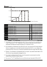
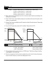
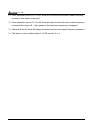
01 - 23 Accel/Decel Time Unit
Factory Setting: 01
Settings 00: Unit is 1 Sec
01: Unit is 0.1 Sec
02: Unit is 0.01 Sec
This parameter sets the resolution of accel/decel time (Pr.01-09 to 01-18).
A high resolution decreases the accel/decel time range as shown in the following chart.