


D-Link DHS-3224V Switch User’s Guide
3
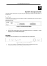
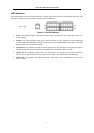
Switch Description and Function
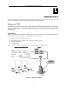
The DHS-3224V VDSL Switch is an Ethernet-based switch capable of delivering VDSL service via installed
telephone cabling. Up to 24 VDSL accounts can be managed per Switch and up to 6 Switches can be set up in a
stacked group configuration. Each Switch paired with an on-site SP-24 DSL Splitter and remote CPE (1 unit per
port). The splitter combines the VDSL data channels and lower frequency analog telephone services (including
ISDN) and transmits the combined services to the end-users. For the VDSL subscriber, the CPE separates the
data and voice channels with a built-in splitter allowing simultaneous, full-duplex VDSL and analog voice
transmission. In this way, Ethernet over VDSL can overlay existing service without additional cable installation
or conditioning.
The Switch functions as a conventional Ethernet switch where each port provides VDSL service to a single
account. The local Ethernet-based network however, differs from standard Ethernet in two significant ways:
Cabling – The Switch provides VDSL service via existing 0.4 mm or 0.5 mm twisted-pair telephone cable.
Reach – VDSL service from the Switch to the subscriber can extend far beyond the maximum reach of standard
Ethernet.
The Switch can be managed via an out-of-band console connection to a computer using terminal emulation
software. The manager console may also be accessed in-band using an SNMP network manager or Telnet.
Management functions will be familiar to users who have worked with Layer 2 Ethernet switches. For users not
familiar with Ethernet switches and switch management, a detailed explanation of some of the important
management concepts and Ethernet standards is provided in Chapter 5.