


D-Link DHS-3224V Switch User’s Guide
52
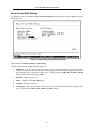
Configure IP Address
Some settings must be entered to allow the Switch to be managed from an SNMP-based Network Management
System such as SNMP v1 or to be able to access the Switch using the Telnet protocol.
The Remote Management Setup screen lets you specify how the Switch will be assigned an IP address to allow
the Switch to be identified on the network.
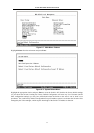
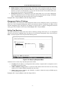
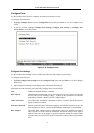
To setup the Switch for remote management, highlight Configure IP Address from the Configuration menu.
The following screen appears:
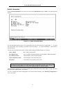
Some settings such as the Switch IP address and subnet mask must be entered to allow the switch to be managed
from an SNMP-based Network Management System or to be able to access the Switch using the TELNET
protocol or the WEB-based Manager. Please see the next chapter for Web-based network management
information.
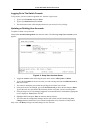
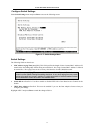
The Remote Management Setup menu lets you specify how the switch will be assigned an IP address to allow
the switch to be identified on the network. In addition, you may specify a subnet mask and default gateway.
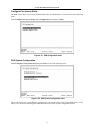
Highlight Remote Management Setup to access the first item on the Configuration menu. The following screen
appears:
Figure 6- 15. Remote Management Setup Screen
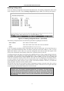
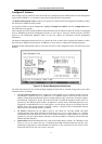
The fields listed under the New Switch Settings heading are those that are currently being used by the switch.
Fields that can be set include:
• Get IP Address From Determines whether the Switch should get its IP Address settings from the
user (Manual), a BOOTP server, or a DHCP server. If Manual is chosen, the Switch will use the IP
Address, Subnet Mask and Default Gateway settings defined in this screen after saving the changes
and rebooting. If BOOTP is chosen, the Switch will send out a BOOTP broadcast request when it is
powered up. The BOOTP protocol allows IP addresses, network masks, and default gateways to be
assigned by a central BOOTP server. If this option is set, the Switch will get its IP settings from the
BOOTP server upon being rebooted. If DHCP is chosen, a Dynamic Host Configuration Protocol
request will be sent when the Switch is rebooted.
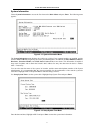
• IP Address Determines the IP address used by the Switch for receiving SNMP and telnet
communications. These fields should be of the form xxx.xxx.xxx.xxx, where each xxx is a number
(represented in decimal) between 0 and 255. This address should be a unique address on a network
assigned to you by the central Internet authorities. The same IP address is shared by both the SLIP and
Ethernet network interfaces.
• Subnet Mask Bitmask that determines the extent of the subnet that the Switch is on. Should be of the
form xxx.xxx.xxx.xxx, where each xxx is a number (represented in decimal) between 0 and 255. If no
subnetting is being done, the value should be 255.0.0.0 for a Class A network, 255.255.0.0 for a Class
B network, and 255.255.255.0 for a Class C network.