


D-Link DHS-3224V Switch User’s Guide
31
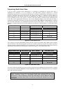
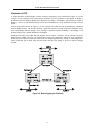
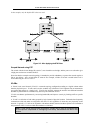
In this example, only the default STP values are used.
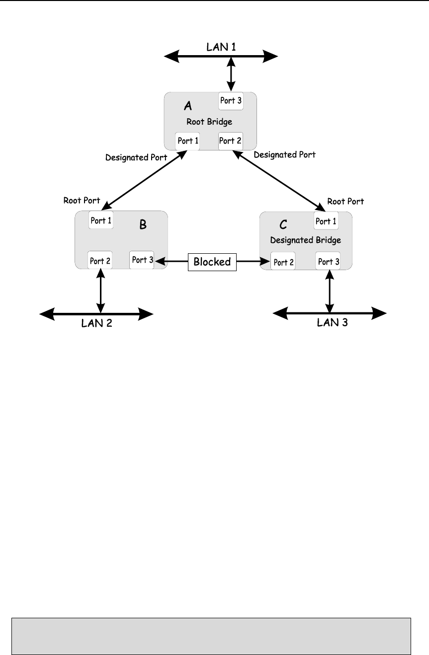
Figure 5-6. After Applying the STA Rules
Sample Network using STP
The switch with the lowest Bridge ID (switch C) was elected the root bridge, and the ports were selected to give
a high port cost between switches B and C.
Note also that the example network topology is intended to provide redundancy to protect the network against a
link or port failure – not a switch failure or removal. For example, a failure of switch A would isolate LAN 1
from connecting to LAN 2 or LAN 3.
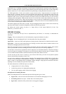
VLANs
A Virtual Local Area Network (VLAN) is a network topology configured according to a logical scheme rather
than the physical layout. VLANs can be used to combine any collection of LAN segments into an autonomous
user group that appears as a single LAN. VLANs also logically segment the network into different broadcast
domains so packets that are forwarded only between ports within the VLAN.
VLANs can enhance performance by conserving bandwidth, and improve security by limiting traffic to specific
domains.
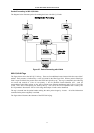
A VLAN is a collection of end nodes grouped by logic instead of physical location. End nodes that frequently
communicate with each other are assigned to the same VLAN, regardless of where they are physically on the
network. Logically, a VLAN can be equated to a broadcast domain, because broadcast packets are forwarded to
only members of the VLAN on which the broadcast was initiated.
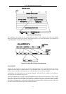
Note: A time saving feature called Asymmetric VLANs can be used by managers that
do not require a complicated or overlapping VLAN setup. See details at the end of this
section.