


D-Link DHS-3224V Switch User’s Guide
36
Configuring VLANs
The switch initially configures one VLAN, VID = 1, called the DEFAULT_VLAN. The factory default setting
assigns all ports on the switch to the DEFAULT_VLAN. As new VLANs are configured, there respective
member ports are removed from the DEFAULT_VLAN.
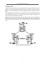
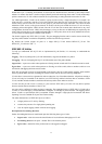
Packets cannot be transmitted accross VLANs. If a member of one VLAN wants to connect to another VLAN,
the link must be through an external router.
If no VLANs are configured on the switch all packets will be forwarded to any destination port. Packets with
unknown source addresses will be flooded to all ports. Broadcast and multicast packets will also be flooded to
all ports.
Broadcast Storms
Broadcast storms consist of broadcast packets that flood and/or are looped on a network causing noticeable
performance degradation and in extreme cases, network failure. Broadcast storms can be caused by
malfunctioning NICs, bad cable connections and applications or protocols that generate broadcast traffic, among
others.
Broadcast storms have long been a concern for network administrators with routers traditionally being used to
prevent their occurrence, and if that failed, limit their scope. However, with the advent of VLANs, switches are
now able to limit broadcast domains better and cheaper than routers. Also, many switches, including the DHS-
3224V, have broadcast sensors and filters built into each port to further control broadcast storms.
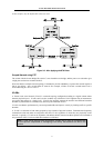
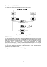
Segmenting Broadcast Domains
VLANs can be used to segment broadcast domains. They do this by forwarding packets only to ports that are
members of the same VLAN. Other parts of the network are effectively shielded. Thus, the smaller the
broadcast domain, the smaller effect a broadcast storm will have. Because VLANs are implemented at each
switch port, they can be quite effective in limiting the scope of broadcast storms.
Eliminating Broadcast Storms
SNMP agents can be programmed to monitor the number of broadcast packets on switch ports and act on the
data. When the number of broadcast packets on a given port rise past an assigned threshold, an action can be
triggered. When enabled, the rate of broadcast packets coming in through the affected port will be limited. Any
traffic above the threshold limit will be discarded. The Switch also supports multicast storm control.
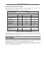
In the Switch, the default trigger threshold is set to 128,000 broadcast packets per second (128 Kbps) for both
100 Mbps Fast Ethernet ports and the optional 1000 Mbps Gigabit Ethernet ports. The thresholds can be set
separately for the two types of ports and can easily be modified by using a normal SNMP management program
or through the console interface.
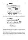
Multicasting
Multicasting enables a single network source to send packets to multiple destinations with persistent
connections. The main advantage to multicasting is to decrease network load for communications that would
otherwise use broadcasting.
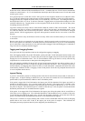
Multicast Groups
There are three types of IP v4 addresses: unicast, broadcast, and multicast. Unicast addresses are used to transmit
messages from a single network device to another, single network device. Broadcast packets are sent to all
devices on the subnetwork. Multicast defines a group of network devices or computers that will receive the
multicast packets. The members of this group are not necessarily on the same subnetwork. Specially designated
multicast addresses are used to send multicast packets to the group members.