


D-Link DHS-3224V Switch User’s Guide
15
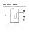
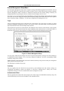
Network Connections to DSL Splitter
The SP-24 DSL Splitter connects VDSL subscribers to both voice and data channels. All interfaces on the DSL
Splitter are female RJ-21 ports. All connection to the DSL Splitter should be made using Telco50 cabling with
male RJ-21 connectors. The DSL Splitter may be connected or disconnected while the Switch is powered on or
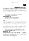
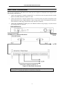
off. Figure 4-4 below illustrates the connection to the DSL Splitter.
Figure 4-4. Connection to the DSL Splitter
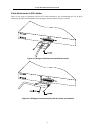
Connect the SP-24 DSL Splitter as follows:
1. Connection(s) to the DHS-3224V Switch are made via the RJ-21 port on the front panel of the device
labeled DSLAM. The Splitter is connected to one VDSL Switch. Connection to the Switch provides the
VDSL data channel (over Ethernet) to end users. Up to 24 VDSL accounts may be connected through
each DSLAM port (24 VDSL subscribers per DSL Splitter).
2. Connection(s) to the PBX are made via the RJ-21 ports labeled PBX. This connects the DSL Splitter to
the PBX and provides the channel for analog voice services.
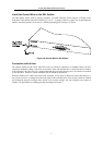
3. Connections to the remote up to 24 CPE are made by first connecting to a Main Distribution Frame,
Cabling Cabinet, patch panels or other suitable wiring systems. Use the RJ-21 ports labeled LINE to
connect the combined data and voice channels to the VDSL accounts.