


D-Link DHS-3224V Switch User’s Guide
30
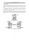
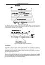
Illustration of STP
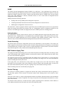
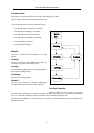
A simple illustration of three Bridges (or three switches) connected in a loop is depicted in Figure 5.5. In this
example, you can anticipate some major network problems if the STP assistance is not applied. If Bridge A
broadcasts a packet to Bridge B, Bridge B will broadcast it to Bridge C, and Bridge C will broadcast it to back to
Bridge A ... and so on. The broadcast packet will be passed indefinitely in a loop, potentially causing a network
failure.
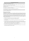
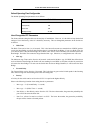
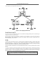
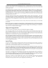
STP can be applied as shown in Figure 5.6. In this example, STP breaks the loop by blocking the connection
between Bridge B and C. The decision to block a particular connection is based on the STP calculation of the
most current Bridge and Port settings. Now, if Bridge A broadcasts a packet to Bridge C, then Bridge C will
drop the packet at port 2 and the broadcast will end there.
Setting-up STP using values other than the defaults, can be complex. Therefore, you are advised to keep the
default factory settings and STP will automatically assign root bridges/ports and block loop connections.
Influencing STP to choose a particular switch as the root bridge using the Priority setting, or influencing STP to
choose a particular port to block using the Port Priority and Port Cost settings is, however, relatively straight
forward.
Figure 5-5. Before Applying the STA Rules