


D-Link DHS-3224V Switch User’s Guide
10
4
Network Connections
This chapter describes how to connect the Switch as a standalone device or in a group to one or more SP-24
Switches. The Switch is provides the Ethernet over VDSL Uplink to the central office while the splitter
combines the VDSL data channel and basic telephone services for transport to end users.
Network cable connections can be made to the Switch with the power on or off. Caution should always be used
when working with or handling any electrically powered devices.
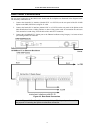
The cable connections described in detail in this chapter include:
Connections to the Switch
• Switch-to-Switch connection via IEEE 1394 “FireWire” for multiple Switch installation
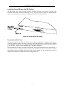
• Switch to backbone; (VDSL over Ethernet) Uplink to backbone via RJ-45 Ethernet port
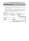
• Switch to SP-24DSL Splitter via Telco50 cable (RJ-21 port)
Connections to SP-24DSL Splitter
• Splitter to Switch or Switch pair via Telco50 (RJ-21 connector) cable
• Splitter to CPE (via 0.4mm or 0.5mm twisted-pair telephone cabling)
• Splitter to PBX (analog channel to Central Office) for basic telephone services
The Switch-to-computer connection via the RS-232 port (used for device/network management) is discussed in
Chapter 5.
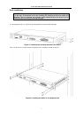
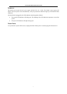
The devices described here are designed for installation in a standard 19” rack where cable connections can be
easily accessed from both the front and the rear of the rack. Please read Chapter 2 for information about how to
install the devices in an equipment rack. The cable connections are described in two sections, one for
connections made using the ports on the front of the equipment and another for the connections made on the
back.
Connecting Multiple Switches
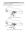
Up to 6 Switches may be grouped in a stacked configuration and connected together using FireWire cabling. A
multiple Switch arrangement can be connected to share a single uplink to the Ethernet backbone and be placed in
a single 19” equipment rack. Stacked switch group interconnections use IEEE 1394 FireWire.
Note: IEEE 1394 “FireWire” is a serial bus technology defined by the IEEE1394 High
Performance Serial Bus standard. For information about IEEE 1394, go to the 1394
Trade Association web site: http://www.1394ta.
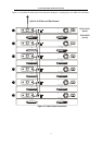
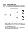
Stacking a Switch Group
Up to 6 Switches may be stacked and managed as a unit with a single IP address and single uplink to the
Ethernet backbone. If you use the stacking function, it is important that you understand how stacking works in
the Switch, read Managing Switch Stacks and Determining Stack Order in Chapter 5 before placing the Switches
in the rack. The auto-detect feature for establishing the stack hierarchy can be overridden, see Stacking
Configuration in Chapter 6 for details on changing the stack order.
Figure 4-2 below illustrates how the Switch stack should be connected.