


D-Link DHS-3224V Switch User’s Guide
5
2
Installation and Setup
Please read this section carefully to be certain that all equipment is installed and set up in accordance with the
instructions given here.
Unpacking
Each shipping carton should contain the following items:
One DHS-3224V VDSL Switch
Mounting kit: 2 mounting brackets and screws
Four self-adhesive rubber feet
One AC power cord
This User’s Guide
If any item is found missing or damaged, please contact your D-LINK representative or sales agent.
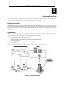
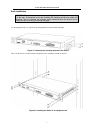
Switch Placement
The Switch and Splitter are designed for mounting in an EIA standard-sized, 19-inch rack, which can be placed
in a wiring closet with other equipment. Make certain the location of the equipment rack is sufficiently dry and
cool. See the Specifications in Appendix A for environmental requirements and limitations. Use these additional
guidelines when selecting a suitable location for the equipment rack.
Attach the rubber feet to all Switches and Splitters that will be installed to maintain a minimum space
between the devices and to avoid damaging the equipment housing.
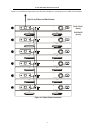
If you are installing more than one Switch, read Connecting Multiple Switches in Chapter 4.
The power outlet should be within 1.82 meters (6 feet) of the device.
Visually inspect the power cord and see that it is secured to the AC power connector.
Make sure that there is proper heat dissipation from and adequate ventilation around the Switch and
Splitter. Leave at least 5cm of space on the right and left sides, as well as 5cm on the rear of the
equipment for ventilation.
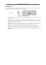
Cables for both devices attach at the front and the rear. Make sure there is ample room at the front and
the back of the devices to access cable connections.
Do not place heavy objects on the Switch or Splitter.