


D-Link DHS-3224V Switch User’s Guide
14
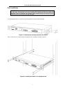
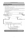
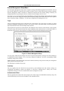
Rear Panel Connections
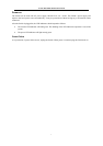
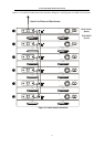
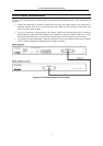
The rear panel connections of the DHS-3224V Switch and SP-24 Splitter are illustrated in the diagram below.
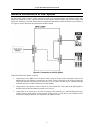
The necessary connections are:
1. Connect the female RJ-21 interface (labeled PSTN A or PSTN B) on the rear panel of the SP-24 DSL
Splitter to the PBX (POTS line) using RJ-21 cable.
2. Connect the female RJ-21 interface (labeled LINE A or LINE B) on the rear panel of the Splitter to the
Main Distribution Frame, Cabling Cabinet or other wiring system used for connection the end users.
This connection is made using Telco50 cable with a male RJ-21 connector.
3. Connect the 10/100BASE-TX Uplink port to the Ethernet backbone using Category 5 or better twisted-
pair cabling with RJ-45 connector.
Figure 4-3. Rear Panel Connections
Note: In Figure 4-3. Rear Panel Connections, a 24-port RJ-11 patch panel is used for
the purpose of illustrating the Splitter-to-subscriber connection.