


D-Link DHS-3224V Switch User’s Guide
24
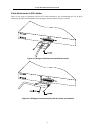
Determining Switch Stack Order
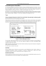
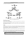
If you are using a stacked switch arrangement it is important to understand how Switch stack order is
established. For illustration, we use an example of four DHS-3224V Switches connected in a stacked
arrangement and booted up. We assume that the Switches are booted up simultaneously and initiate a discovery
process to determine the logical stack order. The logical stack order is a function of MAC address as
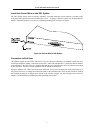
demonstrated below. Once the stack order has been determined, any additions to the stack will affect the stack
order. In addition, the new stack order is a function of the MAC address AND the already established stack
order. That is, the original stack order plays a role in any subsequent changes to the stack when the order is
automatically determined. Auto-detect uses the following formula: MAC Address + Stack Order # to establish
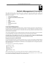
the stack order. When there is no established stack order, the stack order number = 0 in the formula. Using the
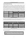
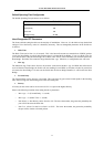
auto-detect stacking function, the four MAC addresses are ordered as listed in Figure 5-4. Initial Stack Order
below:
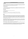
Stack Order
0 MAC Address
MAC + Stack # Stack order after boot up
0 001122334451
001122334451+0 = *51 1 (Master Switch)
0 001122334452 001122334452+0 = *52 2
0 001122334453 001122334453+0 = *53 3
0 001122334454 001122334454+0 = *54 4
0
- -
Not in use
0 - - Not in use
Figure 5-4. Initial Stack Order
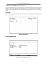
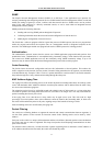
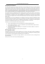
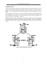
Let us suppose you wish to add another Switch to the stack. The new Switch has a MAC address 001122334450.
The new Switch is first inserted (logically) into the next available position in the stack, the number 5 position.
Then the formula is applied to determine a new stack hierarchy. After rebooting all the Switches in the stack, the
automatically determined stack order appears as listed in the Figure 5-5. New Stack Order below:
Original Stack Order
0 MAC Address
MAC + Stack # New Stack Order
1 001122334451 001122334451+1 = *52 1 (unchanged)
2 001122334452 001122334452+2 = *54 2 (unchanged)
3 001122334453 001122334453+3 = *56 3 (new Switch)
4 001122334454 001122334454+4 = *58 4 (changed from position 3)
5 (new Switch) 001122334450 001122334450+5 = *55 5 (changed from position 4)
6 - - Not in use
Figure 5-5. New Stack Order
You can override the automatic stack order selection to place the newly added Switch into the number 5 position
of the stack order (read Error! Reference source not found. in Chapter 6 for information on how to override the
stack order auto-detect function).
Note: Remember that management of the Switch stack is done only through the Master
Switch. Therefore if there is a new Master Switch after rebooting the new stack
arrangement, it will be necessary to attach the serial cable to the new Master in order to
override the auto-detect stack order or to make any configuration changes to any Switch
in the stack.