


Installation Instructions IM581127000
Spec. No. 581127000 (Model 710NPBA) Issue AB, March 22, 2012
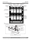
Chapter 5. Installing the Modules and Initially Starting the System Page 97
This document is property of Emerson Network Power, Energy Systems, North America, Inc. and contains confidential and proprietary information owned by Emerson Network Power, Energy
Systems, North America, Inc. Any copying, use, or disclosure of it without the written permission of Emerson Network Power, Energy Systems, North America, Inc. is strictly prohibited.
Checking System Status
Procedure
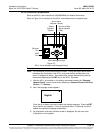
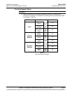
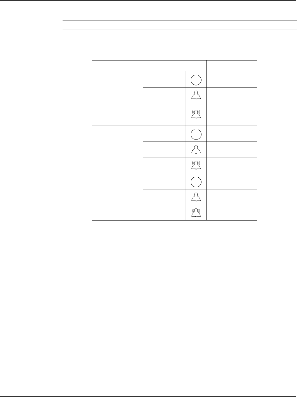
1) Observe the status of the indicators located on the ACU+, rectifiers, and
converters (if furnished). If the system is operating normally, the status of these
is as shown in Table 5-1.
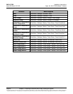
Component
Indicator
Normal State
ACU+
Status
(Green)
On
Minor
(Yellow)
Off
Critical or
Major Alarm
(Red)
Off
Rectifier
Modules
Power
(Green)
On
Protection
(Yellow)
Off
Alarm
(Red)
Off
Converter
Modules
Power
(Green)
On
Protection
(Yellow)
Off
Alarm
(Red)
Off
Table 5-1
Status and Alarm Indicators