


Installation Instructions IM581127000
Spec. No. 581127000 (Model 710NPBA) Issue AB, March 22, 2012
Chapter 4. Making Electrical Connections Page 37
This document is property of Emerson Network Power, Energy Systems, North America, Inc. and contains confidential and proprietary information owned by Emerson Network Power, Energy
Systems, North America, Inc. Any copying, use, or disclosure of it without the written permission of Emerson Network Power, Energy Systems, North America, Inc. is strictly prohibited.
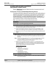
RELAY RACK GROUNDING CONNECTION (FRAME GROUND)
For relay rack grounding requirements, refer to the current edition of the American
National Standards Institute (ANSI) approved National Fire Protection Association's
(NFPA) National Electrical Code (NEC), applicable local codes, and your specific site
requirements.
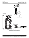
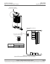
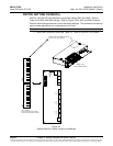
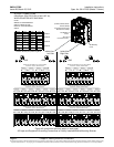
A customer's grounding network lead can be attached to the top of the relay rack.
Provision is made for installing a lead with a two-hole lug that has 1/4" bolt clearance
holes on 5/8" centers. When using 1/4-inch hardware, recommended torque is 84 in-lbs
when a standard flat washer and lock washer are used. Refer to Figure 4-1 for locations.
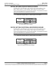
Note: REMOVE TAPE FROM HOLE LOCATIONS BEFORE INSTALLING LUG.
Note: The DC return connection to this system can remain isolated from system frame
and chassis (DC-I).
Note: This system is suitable for installation as part of the Common Bonding Network
(CBN).
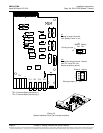
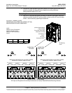
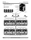
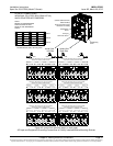
Figure 4-1
Relay Rack Frame Grounding Connection Points
Frame Ground
Connection Point
(1/4” clearance holes on 5/8” centers)
Frame Ground
Connection Point
(1/4” clearance holes on 5/8” centers)
Top View
(Typical Relay Rack)
Top View
(Typical Relay Rack)