


Installation Instructions IM581127000
Spec. No. 581127000 (Model 710NPBA) Issue AB, March 22, 2012
Chapter 2. Installing the System Page 7
This document is property of Emerson Network Power, Energy Systems, North America, Inc. and contains confidential and proprietary information owned by Emerson Network Power, Energy
Systems, North America, Inc. Any copying, use, or disclosure of it without the written permission of Emerson Network Power, Energy Systems, North America, Inc. is strictly prohibited.
MOUNTING SYSTEM COMPONENTS IN AN EQUIPMENT RACK
Note: If the power system was ordered in a relay rack, these procedures have been
performed at the factory.
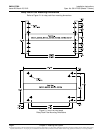
This power system is designed to mount in a standard 23” relay rack having 1” or 1-3/4”
multiple drillings. Refer to System Application Guide SAG581127000 for overall
dimensions and a list of available relay racks.
Mounting the Distribution Cabinet with Module Mounting Assembly
Note: The distribution cabinet is factory connected to the module mounting assembly.
The distribution cabinet with module mounting assembly is mounted as a
complete assembly.
The distribution cabinet with module mounting assembly must be the top-most
component in the rack. Perform the following steps to mount the distribution cabinet with
module mounting assembly.
Danger: The relay rack must be securely anchored to the floor before the
distribution cabinet with module mounting assembly is installed.
The distribution cabinet with module mounting assembly is heavy. Use a
hoist, battery lift, or other appropriate lifting device to raise and support
the assembly during the installation. Take appropriate precautions to
avoid injury.
Procedure
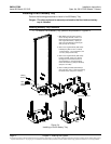
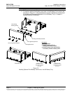
1) Remove the distribution cabinet with module mounting assembly from its
shipping brackets. Position the assembly in the equipment rack. Note that part
of the AC wireways will have to be temporarily removed from the distribution
cabinet to access the mounting hardware.
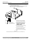
Note: Install the ground washers so the teeth dig into the paint on the mounting
angles. Torque all screws to 65 in-lbs.
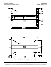
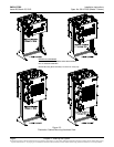
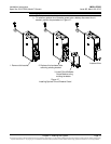
2) Mount the distribution cabinet to the relay rack using the following hardware.
Refer to Figure 2-2.
a) 1-Row Cabinet: Install (8) 12-24 x 1/2" hex head thread-forming screws
(P/N 218710500) and (8) No. 12 ground washers (P/N 215640600).
b) 2-Row Cabinet: Install (10) 12-24 x 1/2" hex head thread-forming screws
(P/N 218710500) and (8) No. 12 ground washers (P/N 215640600).
c) 3-Row Cabinet: Install (12) 12-24 x 1/2" hex head thread-forming screws
(P/N 218710500) and (14) No. 12 ground washers (P/N 215640600).
d) 4-Row Cabinet: Install (16) 12-24 x 1/2" hex head thread-forming screws
(P/N 218710500) and (16) No. 12 ground washers (P/N 215640600).
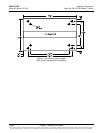
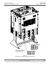
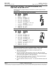
3) Mount the module mounting assembly to the relay rack using hardware as shown
Figure 2-3.