


IM581127000 Installation Instructions
Issue AB, March 22, 2012 Spec. No. 581127000 (Model 710NPBA)
Page 100 Chapter 5. Installing the Modules and Initially Starting the System
This document is property of Emerson Network Power, Energy Systems, North America, Inc. and contains confidential and proprietary information owned by Emerson Network Power, Energy
Systems, North America, Inc. Any copying, use, or disclosure of it without the written permission of Emerson Network Power, Energy Systems, North America, Inc. is strictly prohibited.
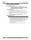
5) Navigate to and select “Set Conv ID”. Press ENT. Use the up or down keys to
change the ACU+ identification number for the flashing converter. Press ENT.
6) Press ESC to return to converter menu screen.
7) Navigate to and select the next converter.
8) Repeat steps 4) through 7) for each of the remaining converters in the system.
9) When you have finished selecting identification numbers for all converters,
repeatedly press ESC to return to the Main Menu.
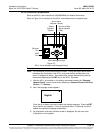
10) Navigate to and select “Manual” (ENT) / “Converter” (ENT) / “All Conv Ctrl”
(ENT).
11) Navigate to “Confirm ID”. Press ENT. “Yes” highlights.
12) Press ENT to select the operation. Press ENT again to confirm.
Note: Check you numbering to be sure it is correct. If there where conflicts in your
numbering, converters with conflicts will be assigned the next available
sequential number.
13) Return to the Main screen by repeatedly pressing ESC (escape).
ACU+ Alarm Relay Check
The following procedures can be used to verify operation of the external alarm relays in a
power system equipped with an ACU+ with the factory default configuration. Note that
alarm relays on an ACU+ with a custom configuration may operate differently.
Note: There are two methods to check alarm relays. The first is by actually causing an
alarm. The second is by using the ACU+ alarm relay check function. The first
method is used in the following procedures. Refer to the ACU+ User Instructions
(UM1M820BNA) for instructions using the ACU+ alarm relay check function.
Checking the AC Fail Alarm and Battery Discharging Alarm Procedure
Note: Battery must be connected during this procedure and there must be at least 20A
of load.
1) Verify system is operating and no alarms are present.
2) Verify the ACU+ displays the Main screen. If not, press ESC repeatedly to return
to the Main screen.
3) Open the external AC disconnects or protective devices that supply power to all
of the rectifiers.
a) Requirement: An audible alarm sounds. Alarm will be silenced in
Requirement d).
b) Requirement: “Protection” indicator on all rectifiers goes from off to yellow.
c) Requirement: ACU+ “Critical/Major” alarm indicator goes from off to red.
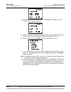
d) Requirement: ACU+ displays “AC Fail” and “Alarm”.
To see the specific alarm, press ENT to display the Main Menu.
Navigate as follows: “Status” (ENT) / “Active Alarm” (ENT).
The Active Alarm screen lists one critical alarm and one minor alarm.
Note that other alarms may be listed.
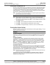
Press ENT. “Batt Group Battery Disch Minor” is displayed.
Note that the above alarm is displayed only if
the system is equipped with a battery shunt.
Use the arrow keys to scroll through the list of alarms.