


Installation Instructions IM581127000
Spec. No. 581127000 (Model 710NPBA) Issue AB, March 22, 2012
Chapter 4. Making Electrical Connections Page 47
This document is property of Emerson Network Power, Energy Systems, North America, Inc. and contains confidential and proprietary information owned by Emerson Network Power, Energy
Systems, North America, Inc. Any copying, use, or disclosure of it without the written permission of Emerson Network Power, Energy Systems, North America, Inc. is strictly prohibited.
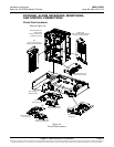
Connections to Field Expansion Module Mounting Assembly
The field expansion module mounting assembly provides separate AC input connections
for each rectifier. Circular openings are provided in the side panels (side feed) and rear
covers (rear feed) of the module mounting assembly for AC input and AC input
equipment-grounding conductors. The openings accept 3/4" inch conduit fittings. AC
input wiring should be provided to all mounting positions intended for rectifiers, including
currently unused positions. This wiring will ease future installation of rectifiers to meet
increased load requirements.
Note: A grounding conductor must be provided with each conduit.
PROCEDURE
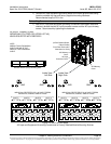
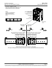
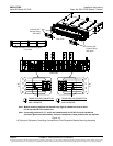
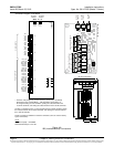
Refer to Figure 4-3 as these procedures are performed.
Accessing Connections and Routing Wire
1) Remove the two AC input access covers from the rear of the module mounting
assembly by first removing the screws that secure them.
2) Install conduit fittings in the side or rear openings as required. Plug buttons are
provided, and must be installed in the openings not being used.
3) Route wiring into the shelf through the previously installed conduit fittings.
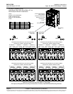
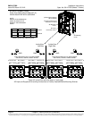
Making AC Input Connections
Note: Module mounting positions are lettered left to right as viewed from the front of
the shelf, A-D in the top row and E-H in the bottom row.
Note: If module mounting positions B, C, F, and G are intended solely for DC-DC
Converter installation (Converter Option must be installed), AC input
connections to these positions are not required.
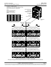
1) Make AC input connections as shown in Figure 4-3. Connect each wire by
inserting the stripped end into the wire opening, and then tightening the screw.
Recommended torque is 10 in-lbs.
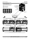
208/240 VAC Service Type:
Line to Line:
Connect Line 1 to Terminal 1.
Connect Line 2 to Terminal 2.
Line to Neutral:
Connect Line to Terminal 1.
Connect Neutral to Terminal 2.
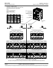
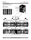
Making AC Equipment Grounding Connections
Note: Make equipment grounding connections to earth ground, not to the branch
circuit neutral conductor.
1) Connect AC input equipment grounding leads to the frame ground studs using
installer-provided ring lugs and factory-supplied mounting hardware.
Recommended torque is 23 in-lbs.
Reinstalling Covers
1) After all AC input and equipment grounding connections have been made and
checked, reinstall the two AC input access covers on the back of the shelf.
Secure with the previously removed screws.