


IM581127000 Installation Instructions
Issue AB, March 22, 2012 Spec. No. 581127000 (Model 710NPBA)
Page 62 Chapter 4. Making Electrical Connections
This document is property of Emerson Network Power, Energy Systems, North America, Inc. and contains confidential and proprietary information owned by Emerson Network Power, Energy
Systems, North America, Inc. Any copying, use, or disclosure of it without the written permission of Emerson Network Power, Energy Systems, North America, Inc. is strictly prohibited.
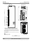
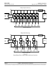
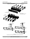
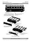
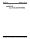
CONTROL BUS CONNECTIONS BETWEEN CONTROLLER
AND MODULE MOUNTING SHELVES
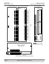
Each module mounting shelf in the system is daisy-chained to the controller. A connector
is located at the top of each shelf and another at the bottom of each shelf. These
connectors are used to interconnect the shelves to the controller. Refer to Figure 4-11
for connector locations. These connections are factory made for shelves factory
installed. The connection must be made if a field expansion shelf is installed as shown in
Figure 4-11.
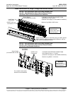
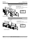
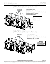
The top connector of the top most module mounting assembly connects to the
controller.
The bottom connector of a shelf plugs into the top connector on the shelf below it.
The bottom connector on the bottom most shelf must have the termination connector.