


IM581127000 Installation Instructions
Issue AB, March 22, 2012 Spec. No. 581127000 (Model 710NPBA)
Page 98 Chapter 5. Installing the Modules and Initially Starting the System
This document is property of Emerson Network Power, Energy Systems, North America, Inc. and contains confidential and proprietary information owned by Emerson Network Power, Energy
Systems, North America, Inc. Any copying, use, or disclosure of it without the written permission of Emerson Network Power, Energy Systems, North America, Inc. is strictly prohibited.
Changing Battery Capacity Rating in the ACU+
To change the battery capacity setting of the ACU+ to match the battery connected to the
power system, perform the following procedure.
Procedure
1) With the Main screen displayed, press ENT to go to the Main Menu. Navigate to
and select “Settings” (ENT).
2) If a password screen opens, a password must be entered to allow the User to
make adjustments. If a password was previously entered and has not yet timed
out, skip this step and proceed to step 3). Otherwise, to enter a password, with
the cursor at the User Name field (default is “Admin”), press the down arrow key
to move cursor down to the password line. Press ENT. “0” is highlighted. Press
the up arrow key once to change the “0” to”1” (default password is “1”), then
press ENT twice. (Note: If you have been assigned a unique User Name and
password, follow this procedure to enter these.)
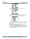
3) With the Settings menu screen displayed, navigate to and select “Battery” (ENT)
/ “Battery 1” (ENT).
4) Navigate to “Rated Capacity”. Press ENT. Use the up or down keys to adjust
the value as required. Press ENT.
5) Return to the Main screen by repeatedly pressing ESC (escape).
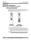
Configuring the ACU+ Identification of Rectifiers and
Assigning which Input Phase is Connected to the Rectifiers
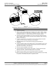
When rectifiers are all installed prior to applying power and starting the system, the order
in which the ACU+ identifies the rectifiers is by serial number (lowest serial number is
Rect 1, next lowest is Rect 2, etc.). If you prefer the ACU+ to identify the rectifiers by
position in the system, perform the following procedure.
Upon power up, the ACU+ arbitrarily assigns Phase A, B, or C to each rectifier. This
assignment is used to display rectifier AC input phase voltage(s). The User may reassign
the phase to each rectifier per your specific installation by following the procedure below.
Procedure
1) With the Main screen displayed, press ENT to go to the Main Menu. Navigate to
and select “Settings” (ENT).
2) If a password screen opens, a password must be entered to allow the User to
make adjustments. If a password was previously entered and has not yet timed
out, skip this step and proceed to step 3). Otherwise, to enter a password, with
the cursor at the User Name field (default is “Admin”), press the down arrow key
to move cursor down to the password line. Press ENT. “0” is highlighted. Press
the up arrow key once to change the “0” to”1” (default password is “1”), then
press ENT twice. (Note: If you have been assigned a unique User Name and
password, follow this procedure to enter these.)
3) With the Settings menu screen displayed, navigate to and select “Rectifier”
(ENT).
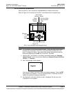
4) Navigate to “Rect #” (# is used here to represent the rectifier identification
number). Press ENT. The rectifier # menu screen is displayed, and the green
LED on one rectifier starts flashing. This is the rectifier currently identified by the
ACU+ as rectifier #. (If this is not the rectifier you want, press ESC to return to
rectifier menu screen and select a different rectifier.)