


Installation Instructions IM581127000
Spec. No. 581127000 (Model 710NPBA) Issue AB, March 22, 2012
Chapter 4. Making Electrical Connections Page 51
This document is property of Emerson Network Power, Energy Systems, North America, Inc. and contains confidential and proprietary information owned by Emerson Network Power, Energy
Systems, North America, Inc. Any copying, use, or disclosure of it without the written permission of Emerson Network Power, Energy Systems, North America, Inc. is strictly prohibited.
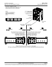
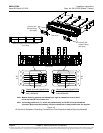
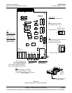
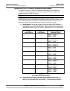
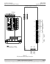
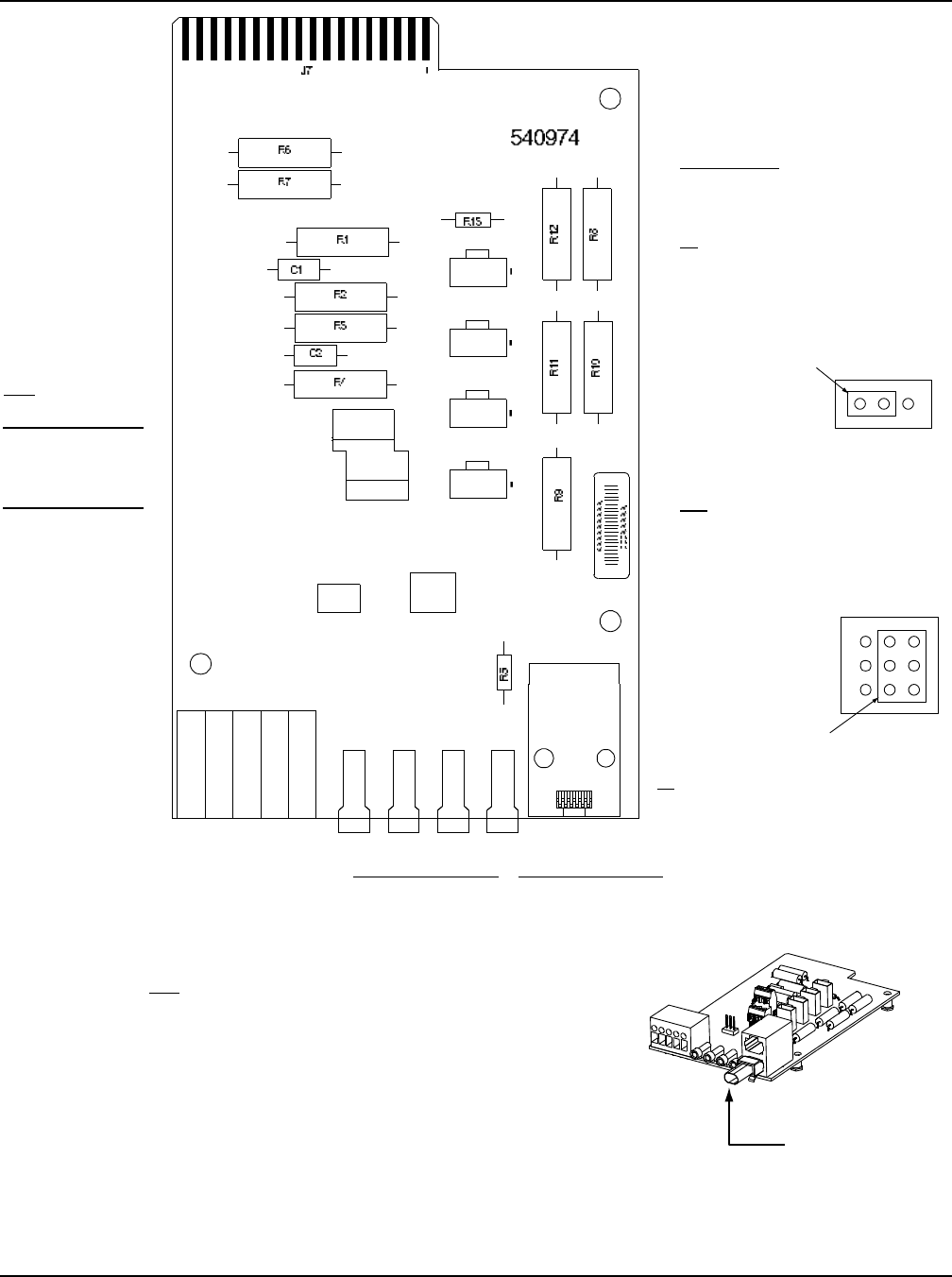
Figure 4-5
System Interface Circuit Card Connections
J5
CAN
TB2
TP3 (+) and TP4 (-)
System Load
Shunt Monitoring
TP1 (+) and TP2 (-)
System Voltage
Monitoring
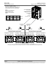
TB1-1: Battery Tray FA
TB1-2: External Battery FA
TB1-3: External System FA
TB1-4: External Battery Monitoring (-)
TB1-5: External Battery Monitoring (+)
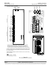
1
1A 2A 3A
1B 2B 3B
5
RS485 Connection
TB2 1A: RS485+
TB2 2A: RS485-
RS232 Connection
TB2 1B: CGND
TB2 2B: TXD232
TB2 3B:RXD232
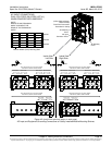
J1
J2
J3
J4
J8
TB2
TB1
TP1 TP2 TP3 TP4
J10
J5
TB1
Wire Size Capacity: 22-12 AWG.
Recommended Torque: 3.0 in-lbs.
FA Signals: Battery applied to the terminal
turns in an alarm.
J1, J2, J3, J4
Distribution Panels FA Inputs
J8
Selects to power Controller
from “Battery Power” or not.
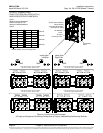
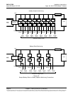
Shorting Jumper
No
Battery
Pwr
Battery
Pwr
External Internal
J8
J10
1
2
3
7
8
9
3 2 1
J10
Battery Monitoring External / Internal
(see TB1-4 and TB1-5 for
external monitoring points)
Shorting Jumper
CAN termination plug
must be installed.
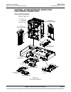
System
Interface
Card