


Installation Instructions IM581127000
Spec. No. 581127000 (Model 710NPBA) Issue AB, March 22, 2012
Table of Contents Page i
This document is property of Emerson Network Power, Energy Systems, North America, Inc. and contains confidential and proprietary information owned by Emerson Network Power, Energy
Systems, North America, Inc. Any copying, use, or disclosure of it without the written permission of Emerson Network Power, Energy Systems, North America, Inc. is strictly prohibited.
TABLE OF CONTENTS
CONTENTS PAGE
IMPORTANT SAFETY INSTRUCTIONS .................................................................................. iv
General Safety .................................................................................................................................................... iv
Voltages .............................................................................................................................................................. iv
Battery ................................................................................................................................................................. iv
Circuit Card Handling ........................................................................................................................................... v
STATIC WARNING ................................................................................................................... vi
CHAPTER 1. GENERAL INFORMATION AND INSTALLATION CHECKLIST ........................ 1
Customer Documentation Package ..................................................................................................................... 1
Installation Acceptance Checklist ........................................................................................................................ 1
CHAPTER 2. INSTALLING THE SYSTEM ................................................................................ 3
General Requirements ......................................................................................................................................... 3
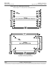
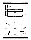
Securing the Relay Rack to the Floor .................................................................................................................. 3
Ventilation Requirements .............................................................................................................................. 3
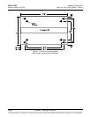
Relay Rack Floor Mounting Dimensions ....................................................................................................... 4
Mounting System Components in an Equipment Rack ....................................................................................... 7
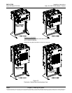
Mounting the Distribution Cabinet with Module Mounting Assembly ............................................................ 7
Installing a List 93 Battery Tray ................................................................................................................... 10
Installing Optional Lug Adapter Busbar Kits, Part Nos. 534449 and 514714 .................................................... 14
Installing Circuit Breakers and Fuses ................................................................................................................ 16
Installing Bullet Nose Type Fuseholders and TPS/TLS Fuses ................................................................... 16
Installing Bullet Nose Type Circuit Breakers ............................................................................................... 18
Installing an Optional Bullet Nose Type 6-Position GMT Distribution Fuse Block ...................................... 19
Installing TPH Fuses ................................................................................................................................... 21
Installing TPL-B Fuses ................................................................................................................................ 22
Installing GJ/218 Circuit Breakers ............................................................................................................... 23
CHAPTER 3. SETTING JUMPERS AND SWITCH OPTIONS ................................................. 28
Circuit Card Locations ........................................................................................................................................ 28
Jumpers on System Interface Circuit Card ........................................................................................................ 29
Controller Power Option .............................................................................................................................. 29
Internal/External Battery Monitoring ............................................................................................................ 29
Switch Settings on IB2 Interface Board ............................................................................................................. 31
Switch Setting on Optional EIB Interface Board ................................................................................................ 31
Switch Setting on SM-DU+ ................................................................................................................................ 34
CHAPTER 4. MAKING ELECTRICAL CONNECTIONS .......................................................... 36
Important Safety Instructions ............................................................................................................................. 36
Wiring Considerations ........................................................................................................................................ 36
Relay Rack Grounding Connection (Frame Ground) ......................................................................................... 37
AC Input and AC Input Equipment Grounding Connections .............................................................................. 38
Connections to Factory Installed Module Mounting Shelves ...................................................................... 38