


Installation Instructions IM581127000
Spec. No. 581127000 (Model 710NPBA) Issue AB, March 22, 2012
Chapter 4. Making Electrical Connections Page 89
This document is property of Emerson Network Power, Energy Systems, North America, Inc. and contains confidential and proprietary information owned by Emerson Network Power, Energy
Systems, North America, Inc. Any copying, use, or disclosure of it without the written permission of Emerson Network Power, Energy Systems, North America, Inc. is strictly prohibited.
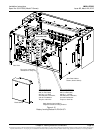
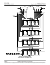
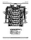
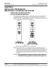
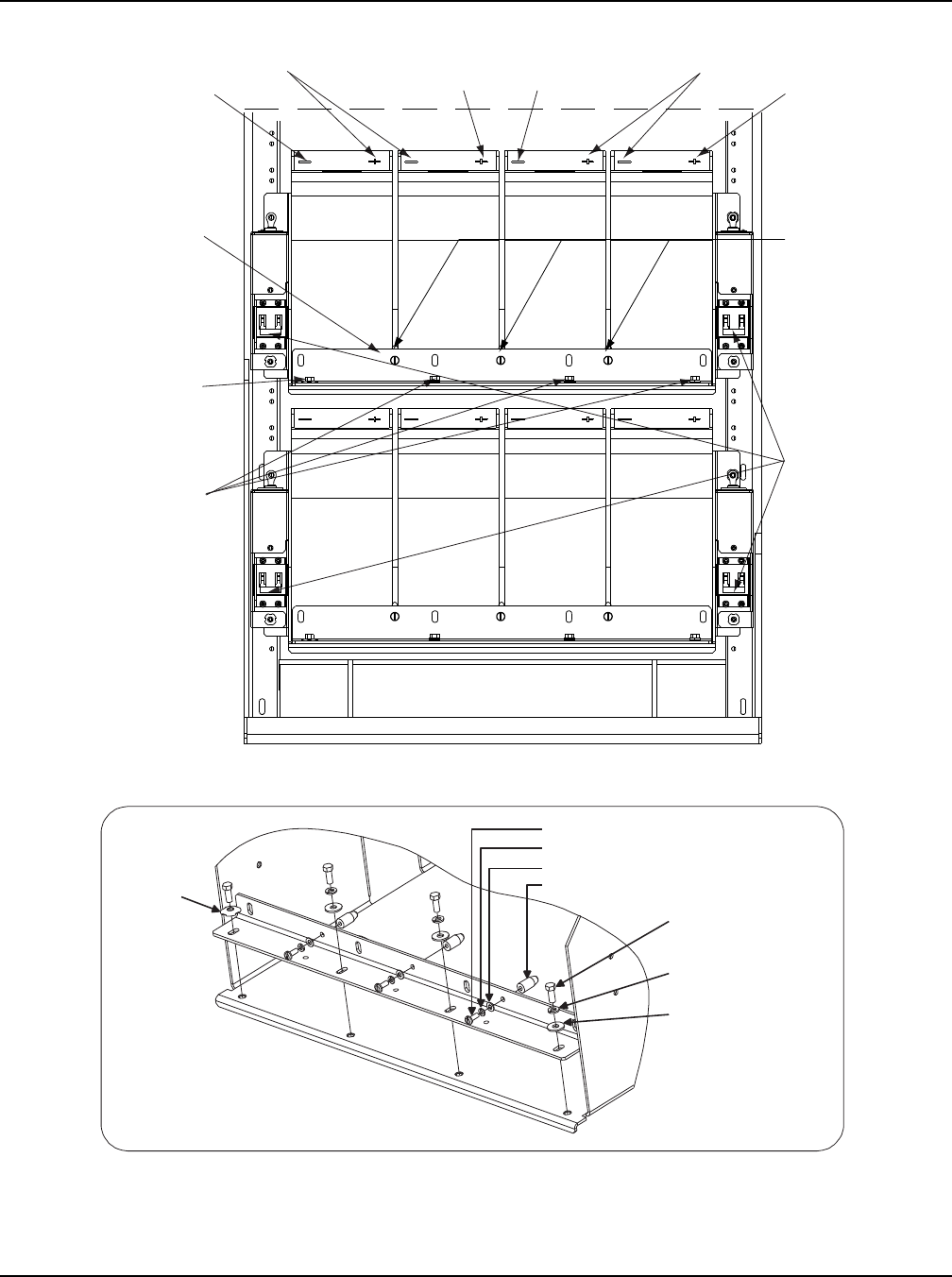
Figure 4-18
List 93 Battery Tray Battery Installation Details
DETAIL A
Alternate Orientation
of Retention Bracket
Spacer (3 Places)
No. 10 Lock Washer (3 Places)
10-32 x 1/2" Pan Head Screw (3 Places)
No. 10 Flat Washer (3 Places)
1/4" Ground
Washer
(1 Place)
1/4-20 x 5/8" Hex
Head Screw
(4 Places)
1/4-20 Lock Washer
(3 Places)
1/4-20 Flat Washer
(3 Places)
Note:
1. Two trays shown as example.
2. Cabling detail omitted.
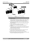
Connect POS (+)
Battery Cable
to this Terminal
(string 2)
Spacers Separate
Batteries (3 places
per tray, front and
back)
Battery Retention
Bracket. See Detail A
for alternate orientation.
1/4-20 X 5/8” Bolt
1/4” Ground Washer
(1 place)
1/4-20 X 5/8” Bolt
1/4” Lock Washer
1/4” Flat Washer
(3 places)
Connect Link Furnished
with Battery to these
Two Terminals
If trays are
equipped with
circuit breakers,
TURN OFF ALL
circuit breakers
before installing
and connecting
any batteries!
Connect POS (+)
Battery Cable
to this Terminal
(string 1)
Connect NEG (-)
Battery Cable
to this Terminal
(string 2)
Connect NEG (-)
Battery Cable
to this Terminal
(string 1)
Connect Link Furnished
with Battery to these
Two Terminals