


IM581127000 Installation Instructions
Issue AB, March 22, 2012 Spec. No. 581127000 (Model 710NPBA)
Page 54 Chapter 4. Making Electrical Connections
This document is property of Emerson Network Power, Energy Systems, North America, Inc. and contains confidential and proprietary information owned by Emerson Network Power, Energy
Systems, North America, Inc. Any copying, use, or disclosure of it without the written permission of Emerson Network Power, Energy Systems, North America, Inc. is strictly prohibited.
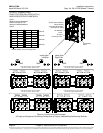
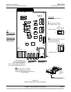
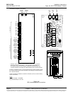
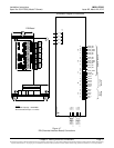
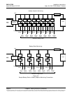
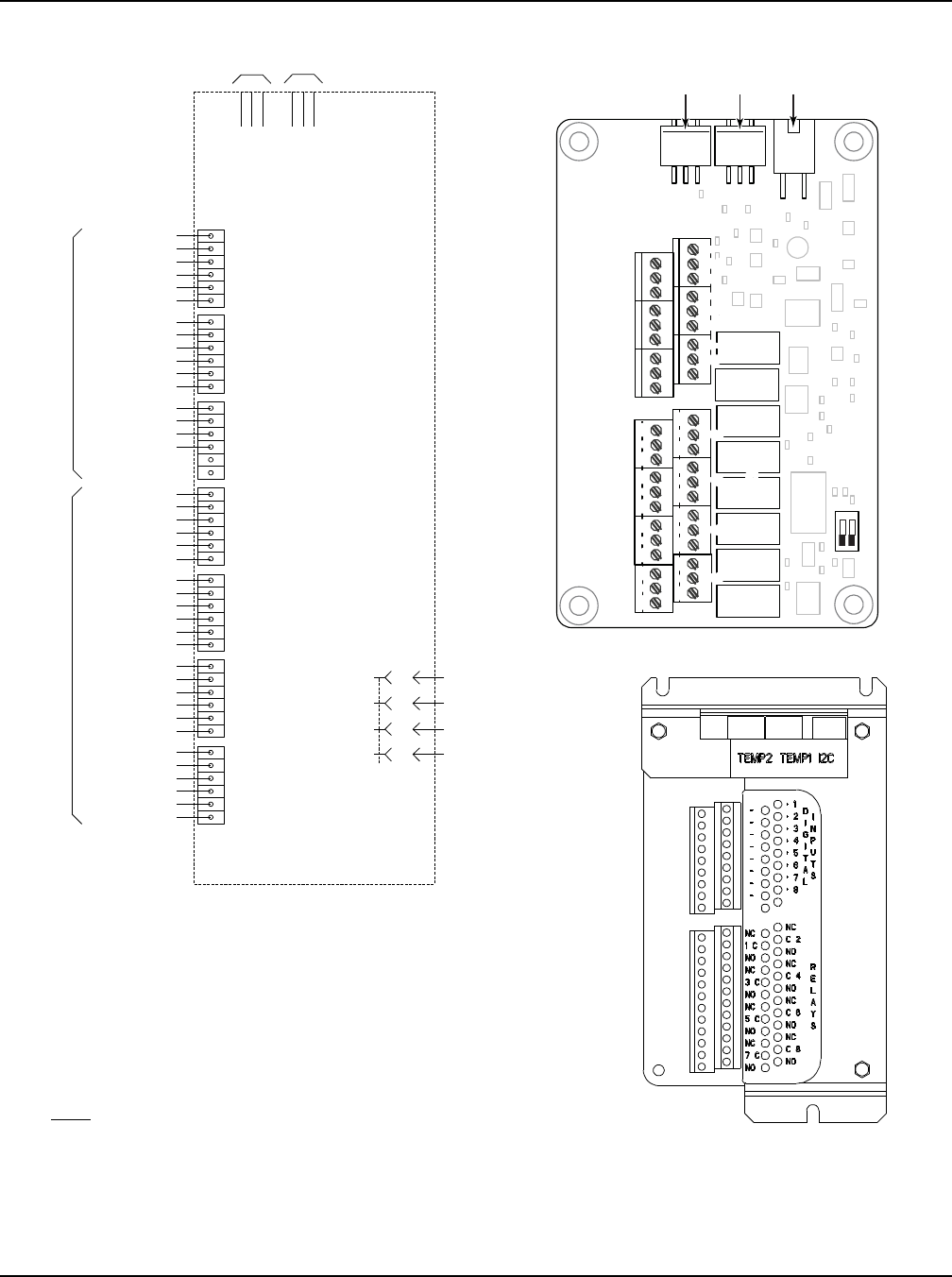
Figure 4-6
IB2 (Interface Board) Connections
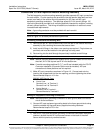
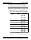
* TheACU+ relay assigned to “Critical Summary” alarm (relay 1 by default)
will operate in the “Fail Safe Mode”. “Fail Safe Mode” means Relay 1 is
de-energized during an alarm condition, opening the contacts between the
C and NO terminals, and closing the contacts between the C and NC terminals.
The ACU+’s remaining seven (7) relays energize during an alarm condition, closing
the contacts between the C and NO terminals, and opening the contacts between
the C and NC terminals.
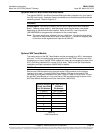
Not all I/O points are available for customer connection (some are used for factory
system connections).
J3-J9:
Wire Size Capacity: 16-26 AWG.
Recommended Torque: 2.2 in-lbs.
MA4C5U31
IB2
DI1-
DI1+
DI2-
DI2+
DI3-
DI3+
J3
J4
J5
J6
J7
J8
J9
DI4-
DI4+
DI5-
DI5+
DI6-
DI6+
DI7-
DI7+
DI8-
DI8+
DO1_NC
DO2_NC
DO1_COM
DO2_COM
DO1_NO
DO2_NO
DO3_NC
DO4_NC
DO3_COM
DO4_COM
DO3_NO
DO4_NO
DO5_NC
DO6_NC
DO5_COM
DO6_COM
DO5_NO
DO6_NO
DO7_NC
DO8_NC
DO7_COM
DO8_COM
DO7_NO
DO8_NO
J11 1
J11 2
J11 3
J12 1
J12 2
J12 3
2
4
3
1
J2
6 5 4 3 2 1 6 5 4 3 2 1 6 5 4 3 2 1 6 5 4 3 2 1 6 5 4 3 2 1 6 5 4 3 2 1 6 5 4 3 2 1
STUPTUOYALER
STUPNILATIGID
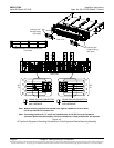
Schematic Diagram of IB2 Board
IB2 TEMP
PROBE 1
IB2 TEMP
PROBE 2
-
J12
*
RELAY
SW1
7
J2
J11
5 3 1
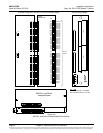
Relay Output Terminal Blocks
Digital InputTerminal BlocksJ9 J8 J7
J6
J5 J4
J3
8 6 4
2
8 7 6 5 4 3
2 1
+
IB2 Board (Top View)
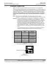
NO C NC
NO C NC
NO C NC
NO C NC
NO C NC
NO C NC
NO C NC
NO C NC
5 3 1
46 2
5
3
1
46 2
5 3 1
46 2
5 3 1
46 2
5 3 1
46 2
5 3 1
46 2
5 3 1
46 2
Connector
toACU+
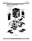
IB2 TEMP
PROBRE 1
IB2 TEMP
PROBE 2
IB2 Board Assembly