


IM581127000 Installation Instructions
Issue AB, March 22, 2012 Spec. No. 581127000 (Model 710NPBA)
Page 44 Chapter 4. Making Electrical Connections
This document is property of Emerson Network Power, Energy Systems, North America, Inc. and contains confidential and proprietary information owned by Emerson Network Power, Energy
Systems, North America, Inc. Any copying, use, or disclosure of it without the written permission of Emerson Network Power, Energy Systems, North America, Inc. is strictly prohibited.
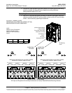
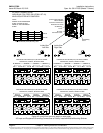
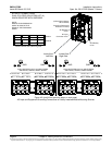
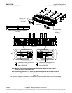
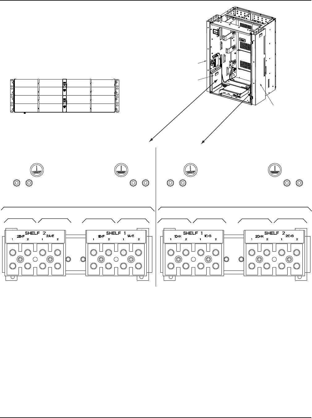
Figure 4-2 (cont’d from previous page, on next page)
AC Input and Equipment Grounding Connections to Factory Installed Module Mounting Shelves
(4-Row Cabinet Shown,
Others Similar)
Front Door Removed in
Illustration for Clarity
AC INPUT CONNECTIONS,
DUAL PCU FEED (581127000 LIST 41),
WHEN EQUIPPED WITH 588705202
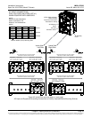
Inside View
Left Side
Inside View
Right Side
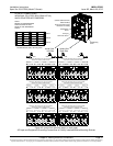
SlotA
Slot E
Slot B
Slot F
Slot C
Slot G
Slot D
Slot H
SlotA
Slot E
Slot B
Slot F
Slot C
Slot G
Slot D
Slot H
Shelf #1
Shelf #2
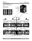
NOTE:
WIRING TO AN EXPANSION
SHELF IS DONE AT THE
REAR OF THE EXPANSION
SHELF.
Rectifier Module (PCU) Mounting Slots
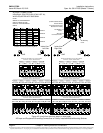
GND GND GND GND
AC 2 AC 2 AC 2 AC 2AC 1 AC 1 AC 1 AC 1
SLOT A & ESLOT B & F
DUAL RECTIFIER (PCU) AC INPUT FEEDS
208-240VAC, 50/60Hz, SINGLE PHASE
SLOT C & GSLOT D & H
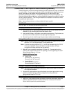
SLOT A & ESLOT B & F
SLOT C & GSLOT D & H
AC 2 AC 2
AC 2 AC 2
AC 1 AC 1
AC 1 AC 1
DUAL RECTIFIER (PCU) AC INPUT FEEDS
208-240VAC, 50/60Hz, SINGLE PHASE
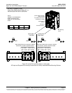
AC Wireway
Cover
AC Wireway
Cover
AC Input
Connector Cover