


Installation Instructions IM581127000
Spec. No. 581127000 (Model 710NPBA) Issue AB, March 22, 2012
Chapter 5. Installing the Modules and Initially Starting the System Page 101
This document is property of Emerson Network Power, Energy Systems, North America, Inc. and contains confidential and proprietary information owned by Emerson Network Power, Energy
Systems, North America, Inc. Any copying, use, or disclosure of it without the written permission of Emerson Network Power, Energy Systems, North America, Inc. is strictly prohibited.
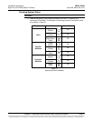
“Rect AC Mains Failure Critical” is displayed.
Note that other alarms may be displayed.
e) Requirement: External “Relay 1 Critical Summary Alarm”, “Relay 6 Mains
Failure Alarm”, and “Relay 13 Battery Discharge Alarm” (requires EIB
Interface Board to be installed in the system) activate.
4) Return external AC disconnects or protective devices to the ON position. Note
that you may get a “Battery Current Limit Exceeded” alarm for a short duration
depending on how long this test was performed and the condition of the battery.
a) Requirement: “Power” indicator on all rectifiers goes from off to green.
b) Requirement: ACU+ “Critical/Major” alarm indicator goes from red to off.
c) Requirement: Press ESC repeatedly to return to the Main screen. ACU+
displays “No Alm”.
d) Requirement: All external alarms deactivate.
Checking Rectifier Alarm Procedure
1) Verify system is operating and no alarms are present.
2) Verify the ACU+ displays the Main screen. If not, press ESC repeatedly to return
to the Main screen.
3) Pull one rectifier half way out of the shelf. To do this, first loosen the captive
screw on the module handle. Pull the handle to pivot it out of the module front
panel (this will also retract the latch mechanism located at the right side of the
module). Refer to Figure 5-2 for latch mechanism illustration.
a) Requirement: An audible alarm sounds. Alarm will be silenced in
Requirement c).
b) Requirement: ACU+ “Critical/Major” alarm indicator goes from off to red.
c) Requirement: ACU+ displays “Alarm”.
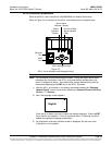
To see the specific alarm, press ENT to display the Main Menu.
Navigate as follows: “Status” (ENT) / “Active Alarm” (ENT).
The “Active Alarm” screen lists one major alarm.
Press ENT. “Rect ### Comm Fail Major” is displayed.
d) Requirement: External “Relay 2 Major Summary Alarm” and “Relay 8
Rectifier Major Alarm” activate.
Note: If the system is equipped with only one rectifier, skip step 4).
4) Pull a second rectifier half way out of the shelf, as described in Step 3).
a) Requirement: An audible alarm sounds. Alarm will be silenced in
Requirement c).
b) Requirement: ACU+ “Critical/Major” alarm indicator stays red.
c) Requirement: Press ESC repeatedly to return to the Main screen. ACU+
displays “Alarm”.
To see the specific alarm, press ENT to display the Main Menu.
Navigate as follows: “Status” (ENT) / “Active Alarm” (ENT).
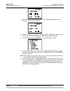
The Active Alarm screen lists one critical and two major alarms.
Press ENT. “Rect Group Multi-Rect Fail Critical” is displayed.
Use the arrow keys to scroll through the list of alarms.
“Rect ### Comm Fail Major” is displayed for each removed rectifier.