


IM581127000 Installation Instructions
Issue AB, March 22, 2012 Spec. No. 581127000 (Model 710NPBA)
Page 48 Chapter 4. Making Electrical Connections
This document is property of Emerson Network Power, Energy Systems, North America, Inc. and contains confidential and proprietary information owned by Emerson Network Power, Energy
Systems, North America, Inc. Any copying, use, or disclosure of it without the written permission of Emerson Network Power, Energy Systems, North America, Inc. is strictly prohibited.
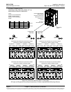
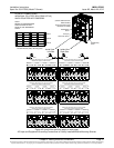
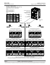
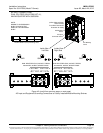
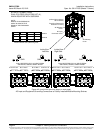
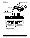
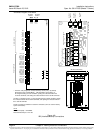
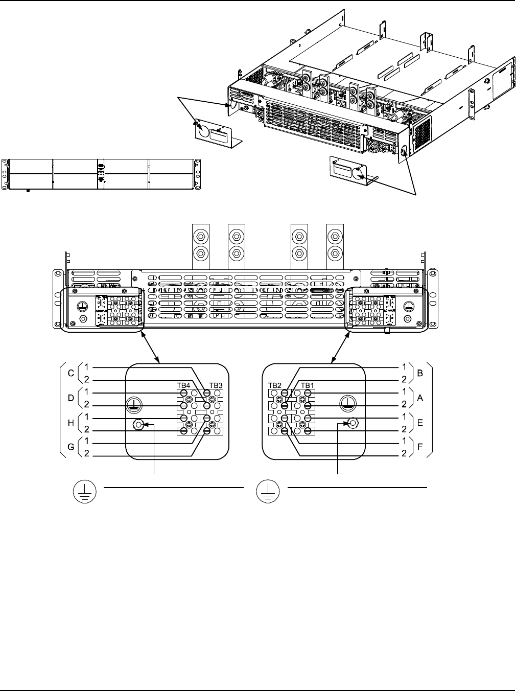
Figure 4-3
AC Input and Equipment Grounding Connections to Field Expansion Module Mounting Assembly
SlotA
Slot E
Slot B
Slot F
Slot C
Slot G
Slot D
Slot H
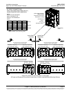
AC
IN
AC
IN
Rectifier Module (PCU) Mounting Slots
Front View
Holes for 3/4"
Conduit Fitting
(AC Input)
Holes for 3/4"
Conduit Fitting
(AC Input)
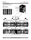
Rear View
Rear View
FRAME GROUND CONNECTION
ONE 10-32 X 3/4" STUD
AND HARDWARE
FRAME GROUND CONNECTION
ONE 10-32 X 3/4" STUD
AND HARDWARE
Note: Module mounting positions are lettered left to right as viewed from front o f shelf,
A-D in top row and E-H in bottom row.
Note: If mounting positions B, C, F, and G are intended solely for DC-DC Converter installation
(Converter Option must be installed), AC input connections to these positions are not required.