


Installation Instructions IM581127000
Spec. No. 581127000 (Model 710NPBA) Issue AB, March 22, 2012
Chapter 2. Installing the System Page 3
This document is property of Emerson Network Power, Energy Systems, North America, Inc. and contains confidential and proprietary information owned by Emerson Network Power, Energy
Systems, North America, Inc. Any copying, use, or disclosure of it without the written permission of Emerson Network Power, Energy Systems, North America, Inc. is strictly prohibited.
CHAPTER 2.
INSTALLING THE SYSTEM
GENERAL REQUIREMENTS
This product is intended only for installation in a Restricted Access Location on or
above a non-combustible surface.
This product must be located in a Controlled Environment with access to Crafts
persons only.
This product is intended for installation in Network Telecommunication Facilities (CO,
vault, hut, or other environmentally controlled electronic equipment enclosure).
This product is intended for connection to the common bonding network in a Network
Telecommunication Facility (CO, vault, hut, or other environmentally controlled
electronic equipment enclosure).
The installer should be familiar with the installation requirements and techniques to
be used in securing the relay rack to the floor.
Clearance requirements are:
a) Recommended minimum aisle space clearance for the front of the relay rack is
2' 6".
b) Recommended minimum aisle space clearance for the rear of the relay rack is
2’ 0” for any of the following conditions:
1) Addition of a Module Mounting Assembly in the field.
2) Making AC input connections to the field expansion Module Mounting
Assembly.
For all other conditions, recommended minimum aisle space clearance for the rear of
the relay rack is that which is specified for proper module mounting assembly
ventilation. Refer to Module Mounting Assembly Power Data Sheet PD588705200
(PD588705201, PD588705202, PD588705203, PD588705204) for ventilation
spacing requirements.
Note: Minimum spacing specified for ventilation may not permit replacement of
certain components such as module mounting shelves.
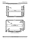
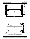
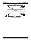
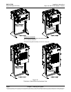
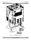
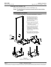
SECURING THE RELAY RACK TO THE FLOOR
All equipment cabinets are factory mounted to the relay rack or shipping brackets
specified when ordered.
Secure the relay rack to the floor per site requirements. Refer to the General
Requirements section at the beginning of this chapter.
Ventilation Requirements
Refer to the General Requirements section at the beginning of this chapter.