


IM581127000 Installation Instructions
Issue AB, March 22, 2012 Spec. No. 581127000 (Model 710NPBA)
Page 34 Chapter 3. Setting Jumpers and Switch Options
This document is property of Emerson Network Power, Energy Systems, North America, Inc. and contains confidential and proprietary information owned by Emerson Network Power, Energy
Systems, North America, Inc. Any copying, use, or disclosure of it without the written permission of Emerson Network Power, Energy Systems, North America, Inc. is strictly prohibited.
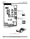
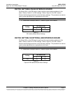
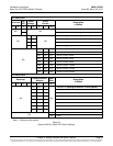
SWITCH SETTING ON SM-DU+
SM-DU+ uses two (2) 8-bit switches for parameter setting (SW1 and SW2). Refer to
Table 3-3 for SW1 and SW2 settings. Refer to Figure 3-5 for SW1 and SW2 locations.
Perform the following procedure to verify the factory settings. This procedure can also be
used to make adjustments on a replacement circuit card.
Procedure
1) Ensure SW1 and SW2 are set per Table 3-3. Refer to Figure 3-5 for location.
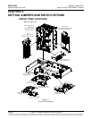
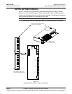
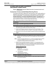
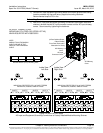
Figure 3-5
Optional SM-DU+ Switch Location and Settings
SM-DU+ and
Shunt Interface Board
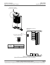
SM-DU+
Switches SW1 and SW2 are located
in this corner of the SM-DU+.
SW1 SW2
on
5 6 7 81 2 3 4
off
on
5 6 7 81 2 3 4
off
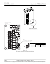
power
can RS485 RS485
SHUNT SHUNT FUSE
RS232
SW1 SW2
J1
J7 J8 J6
J3 J4 J4A
J5
ON
OFF
1 2 34 56 7 8 1 23 45 6 7 8
RedIndicator
Yellow Indicator
Green Indicator
SW1 and SW2
In this system, switch settings
must be in the positions shown.