


IM581127000 Installation Instructions
Issue AB, March 22, 2012 Spec. No. 581127000 (Model 710NPBA)
Page 56 Chapter 4. Making Electrical Connections
This document is property of Emerson Network Power, Energy Systems, North America, Inc. and contains confidential and proprietary information owned by Emerson Network Power, Energy
Systems, North America, Inc. Any copying, use, or disclosure of it without the written permission of Emerson Network Power, Energy Systems, North America, Inc. is strictly prohibited.
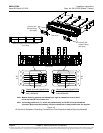
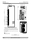
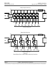
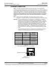
total of eight (8) DC voltage inputs for these connections. An alarm is issued
when either battery block voltage or battery midpoint voltage is abnormal.
Refer to Figure 4-8 for connection details. Refer to the ACU+ User Instructions
(UM1M820BNA) and program the following parameters found in the EIB menu.
Battery Block Monitoring
Voltage Type: Set to “24 (Block 2)”. This selects the EIB to monitor up to
four (4) 24V battery strings with two (2) 12V blocks per string
BlockVDiff(12V): This menu item appears if “24 (Block 2)” is selected above.
Set to the alarm threshold for battery block monitoring per site requirements.
The ACU+ issues an alarm when any block voltage of any battery string has
an abnormal value. The alarm is issued when the difference between any
block voltage and a reference voltage is greater than the value of the block
voltage difference setting.
Block In-Use: Set to the number of 12V battery blocks being used.
Midpoint Monitoring
Voltage Type: Set to “Midpoint”. This selects the EIB to monitor the midpoint
voltage of up to eight (8) battery strings.
BlockVDiff(Mid): This menu item appears if “Midpoint” is selected above.
Set to the alarm threshold for battery midpoint monitoring per site
requirements. The ACU+ issues an alarm when any battery midpoint voltage
of any battery string has an abnormal value. The alarm is issued when the
difference between any battery midpoint voltage and a reference voltage is
greater than the value of the block voltage difference setting.
Block In-Use: Set to number of 12V battery blocks being used.
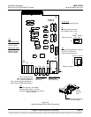
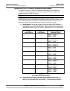
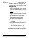
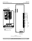
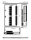
c) Programmable Relay Outputs: The EIB (ACU+ Controller Extended Interface
Board) provides five programmable alarm relays with Form-C contacts.
Note: The relays energize during an alarm condition, closing the contacts
between the C and NO terminals, and opening the contacts between the
C and NC terminals.
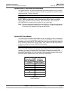
The default ACU+ configuration programs these relays as follows. Refer to the
ACU+ User Instructions (UM1M820BNA) for programming information.
Relay 9: Converter Critical Alarm (multiple converter fail alarms)
Relay 10: Converter Major Alarm (single converter fail alarm)
Relay 11: Rectifier Critical Alarm (multiple rectifier fail alarms)
Relay 12: High 2 Battery Temp Alarm
Relay 13: Battery Discharge Alarm
Temperature Probes: Temperature probes are connected to the optional EIB (ACU+
Controller Extended Interface Board) mounted inside the distribution cabinet. Refer to
“Temperature Probes” in the previous section.