


Installation Instructions IM581127000
Spec. No. 581127000 (Model 710NPBA) Issue AB, March 22, 2012
Chapter 4. Making Electrical Connections Page 59
This document is property of Emerson Network Power, Energy Systems, North America, Inc. and contains confidential and proprietary information owned by Emerson Network Power, Energy
Systems, North America, Inc. Any copying, use, or disclosure of it without the written permission of Emerson Network Power, Energy Systems, North America, Inc. is strictly prohibited.
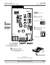
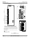
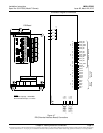
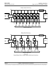
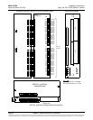
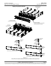
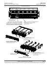
Optional SM-DU+ and Shunt Interface Board
The optional SM-DU+ and Shunt Interface Board provides connections for up to twenty-
five (25) shunt inputs. Inputs are factory connected to any distribution positions/devices
containing shunts. Refer to Figure 4-9.
Procedure
Current Inputs: Connect up to twenty-five (25) shunt inputs to the Shunt Interface
Board. Observe proper polarity. Note that some inputs may be factory connected,
depending on distribution devices installed. Refer to the ACU+ User Instructions
(UM1M820BNA) for programming information for the unused inputs.
Note: The shunt needs to be installed in the hot (+24V) bus. Connect the plus side of
the shunt to the positive shunt input on the SM-DU+. Connect the negative side
of the shunt to the negative shunt input on the SM-DU+.
Optional SM-Temp Module
The analog output of the SM-Temp Module may be connected to an ACU+ temperature
port input. In lieu of connecting the analog output of the SM-TEMP module to an ACU+
temperature port input, the SM-TEMP module can simply be connected at the end of the
ACU+ CAN bus (requires ACU+ version 3.02 or later). Refer to the SM-Temp Module
Installation and User instructions (UM547490) for details.
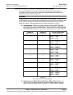
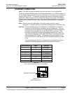
CAN Bus Procedure
Remove the CAN termination plug from the bottom CAN connector on the System
Interface circuit card. Connect the SM-Temp Module CAN bus to the bottom CAN
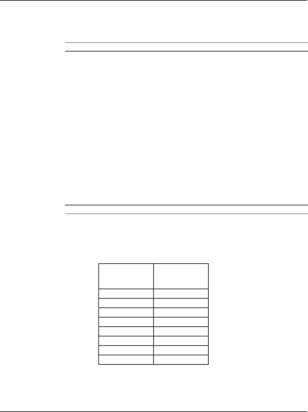
connector on the System Interface circuit card. Refer to Table 4-3 for pin-outs. Ensure
the last SM-Temp Module (or if only one) has a CAN termination strap as shown in the
SM-Temp Module Installation and User instructions (UM547490).
System Interface
Circuit Card CAN
Port Pin Number
SM-Temp Module
CAN Port
Pin Number
1 (CAN L)
TB1-3 (CAN L)
2 (CAN H)
TB1-3 (CAN H)
3
--
4
--
5
--
6
--
7
--
8
--
Table 4-3
CAN Connections