


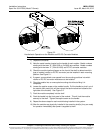
IM581127000 Installation Instructions
Issue AB, March 22, 2012 Spec. No. 581127000 (Model 710NPBA)
Page 90 Chapter 5. Installing the Modules and Initially Starting the System
This document is property of Emerson Network Power, Energy Systems, North America, Inc. and contains confidential and proprietary information owned by Emerson Network Power, Energy
Systems, North America, Inc. Any copying, use, or disclosure of it without the written permission of Emerson Network Power, Energy Systems, North America, Inc. is strictly prohibited.
CHAPTER 5.
INSTALLING THE MODULES
AND INITIALLY STARTING THE SYSTEM
INSTALLING THE RECTIFIER AND
DC-DC CONVERTER MODULES
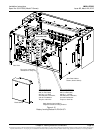
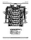
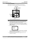
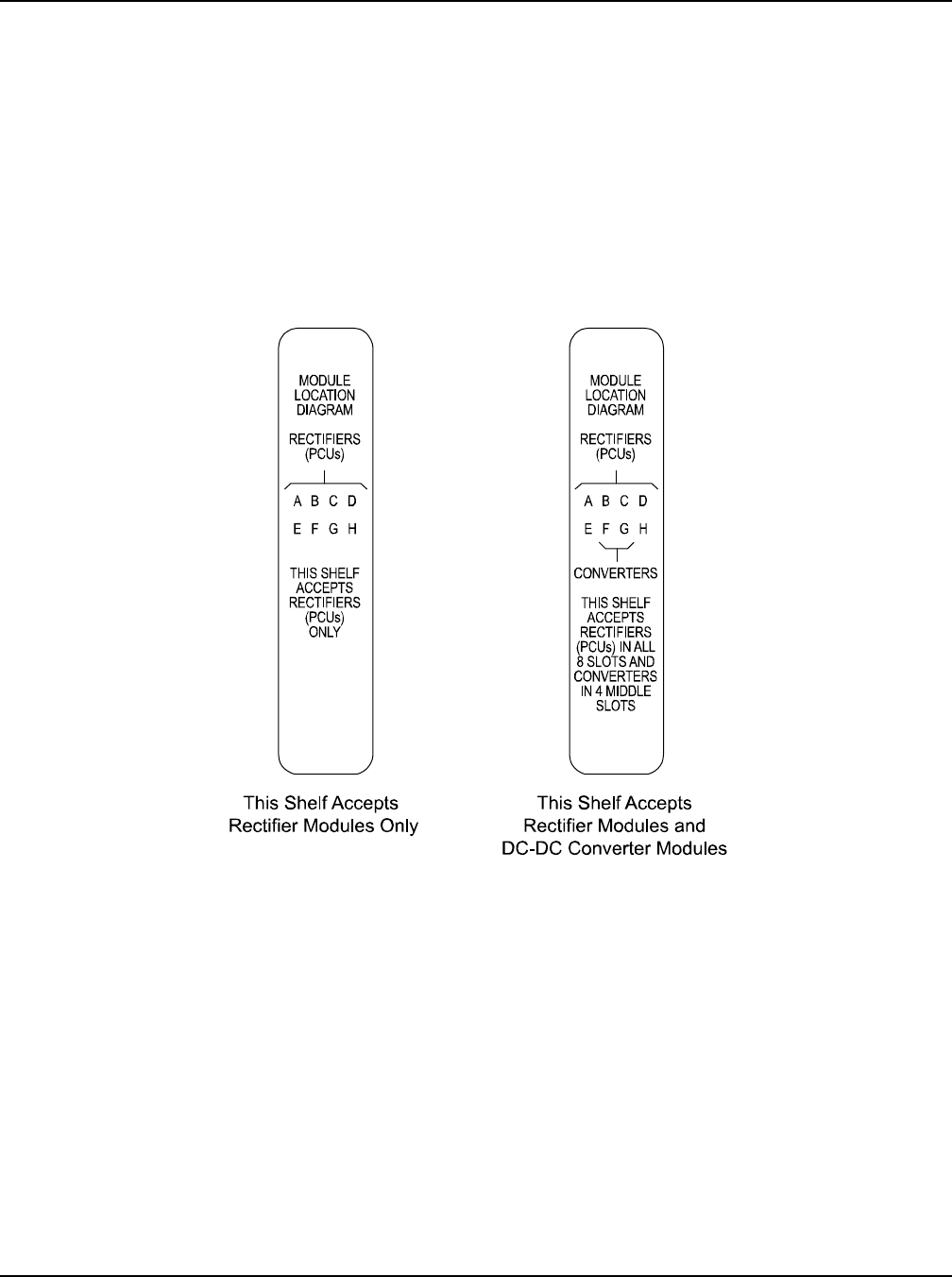
The module location diagram on the front of each shelf shows which type modules can
be operated in that shelf. (See Figure 5-1.) Rectifiers will operate in any mounting
position in any shelf. If a shelf accepts DC-DC converter modules, they must be installed
in any or all of the four middle mounting positions.
Figure 5-1
Module Location Diagrams (on the front of each shelf)
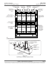
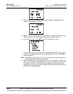
Note: Each rectifier and DC-DC converter module locks into the module mounting
assembly by means of a latch located on the right-hand side of the module. The
latch and module handle are interactive. Pushing the handle into the module front
panel causes the latch to extend to the locking position; pulling the handle out
from the module front panel causes the latch to retract. See Figure 5-2 for handle
operation.
Warning: To prevent damage to the latching mechanism, ensure the handle is in
the open position when installing or removing a module. NEVER hold
the handle in the closed position when installing a module into a shelf.