


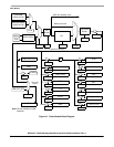
Clock Module
MCF52211 ColdFire® Integrated Microcontroller Reference Manual, Rev. 2
6-8 Freescale Semiconductor
14–12
MFD
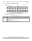
Multiplication Factor Divider. Contain the binary value of the divider in the PLL feedback loop. The MFD[2:0]
value is the multiplication factor applied to the reference frequency. When MFD[2:0] are changed or the PLL
is disabled in stop mode, the PLL loses lock. In 1:1 PLL mode, MFD[2:0] are ignored, and the multiplication
factor is one.
Note: In external clock mode, the MFD[2:0] bits have no effect.
11
LOCRE
Loss-of-clock reset enable. Determines how the system manages a loss-of-clock condition. When the
LOCEN bit is clear, LOCRE has no effect. If the LOCS flag in SYNSR indicates a loss-of-clock condition,
setting the LOCRE bit causes an immediate reset. To prevent an immediate reset, the LOCRE bit must be
cleared before entering stop mode with the PLL disabled.
0 No reset on loss-of-clock
1 Reset on loss-of-clock
Note: In external clock mode, the LOCRE bit has no effect.
10–8
RFD
Reduced frequency divider field. The binary value written to RFD[2:0] is the PLL frequency divisor; see
table in MFD bit description. Changing RFD[2:0] does not affect the PLL or cause a relock delay. Changes
in clock frequency are synchronized to the next falling edge of the current system clock. To avoid surpassing
the allowable system operating frequency, write to RFD[2:0] only when the LOCK bit is set.
7
LOCEN
Enables the loss-of-clock function. LOCEN does not affect the loss-of-lock function.
0 Loss-of-clock function disabled
1 Loss-of-clock function enabled
Note: In external clock mode, the LOCEN bit has no effect
.
6
DISCLK
Disable CLKOUT determines whether CLKOUT is driven. Setting the DISCLK bit holds CLKOUT low.
0 CLKOUT enabled
1 CLKOUT disabled
Table 6-5. SYNCR Field Descriptions (continued)
Field Description
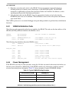
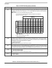
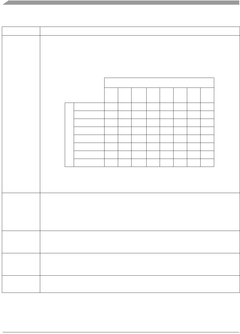
The following table shows the system frequency multiplier of the reference
frequency
1
in normal PLL mode.
1
f
sys
= f
ref
× 2(MFD + 2) / 2
RFD
; f
ref
× 2(MFD + 2) ≤ (Max_Spec) MHz, f
sys
≤
(Max_Spec) MHz
MFD[2:0]
000
2
(4x)
2
MFD = 000 not valid for f
ref
< 3 MHz
001
3
(6x)
3
Default value out of reset
010
(8x)
011
(10x)
100
(12x)
101
(14x)
110
(16x)
111
(18x)
RFD[2:0]
000
3
(÷ 1) 4 6
3
8 1012141618
001 (÷ 2) 23 4 56789
010 (÷ 4) 1 3/2 2 5/2 3 7/2 4 9/2
011 (÷ 8) 1/2 3/4 1 5/4 3/2 7/4 2 9/4
100 (÷ 16) 1/4 3/8 1/2 5/8 3/4 7/8 1 9/8
101 (÷ 32) 1/8 3/16 1/4 5/16 3/8 7/16 1/2 9/16
110 (÷ 64) 1/16 3/32 1/8 5/32 3/16 7/32 1/4 9/32
111 (÷ 128) 1/32 3/64 1/16 5/64 3/32 7/64 1/8 9/64