


Pulse-Width Modulation (PWM) Module
MCF52211 ColdFire® Integrated Microcontroller Reference Manual, Rev. 2
Freescale Semiconductor 27-21
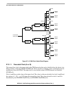
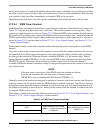
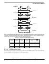
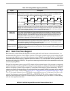
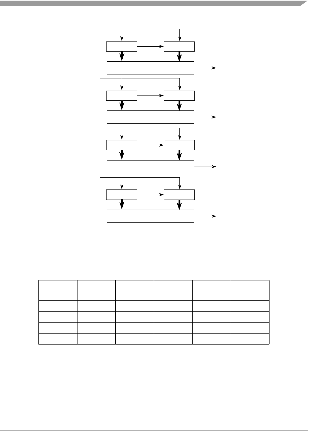
Figure 27-20. PWM 16-Bit Mode
Left- or center-aligned output mode can be used in concatenated mode and is controlled by the low order
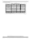
CAEn bit. The high order CAEn bit has no effect. The table shown below is used to summarize which
channels are used to set the various control bits when in 16-bit mode.
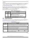
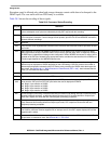
27.3.2.8 PWM Boundary Cases
The following table summarizes the boundary conditions for the PWM regardless of the output mode (left-
or center-aligned) and 8-bit (normal) or 16-bit (concatenation):
Table 27-15. 16-bit Concatenation Mode Summary
CONnn PWMEn PPOLn PCLKn CAEn
PWMn
Output
CON67 PWM7 PPOL7 PCLK7 CAE7 PWMOUT7
CON45 PWM5 PPOL5 PCLK5 CAE5 PWMOUT5
CON23 PWME3 PPOL3 PCLK3 CAE3 PWMOUT3
CON01 PWME1 PPOL1 PCLK1 CAE1 PWMOUT1
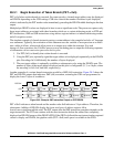
PWMCNT4
PWMOUT5
High Low
Period/Duty Compare
PWMCNT5
Clock Source 5
PWMCNT2
PWMOUT3
High Low
Period/Duty Compare
PWMCNT3
Clock Source 3
PWMCNT0
PWMOUT1
High Low
Period/Duty Compare
PWMCNT1
Clock Source 1
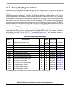
PWMCNT6
PWMOUT7
High Low
Period/Duty Compare
PWMCNT7
Clock Source 7