


Queued Serial Peripheral Interface (QSPI)
MCF52211 ColdFire® Integrated Microcontroller Reference Manual, Rev. 2
23-4 Freescale Semiconductor
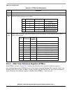
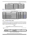
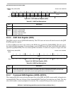
Table 23-3. QMR Field Descriptions
Field Description
15
MSTR
Master mode enable.
0 Reserved, do not use.
1 The QSPI is in master mode. Must be set for the QSPI module to operate correctly.
14
DOHIE
Data output high impedance enable. Selects QSPI_DOUT mode of operation.
0 Default value after reset. QSPI_DOUT is actively driven between transfers.
1 QSPI_DOUT is high impedance between transfers.
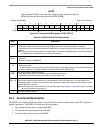
13–10
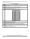
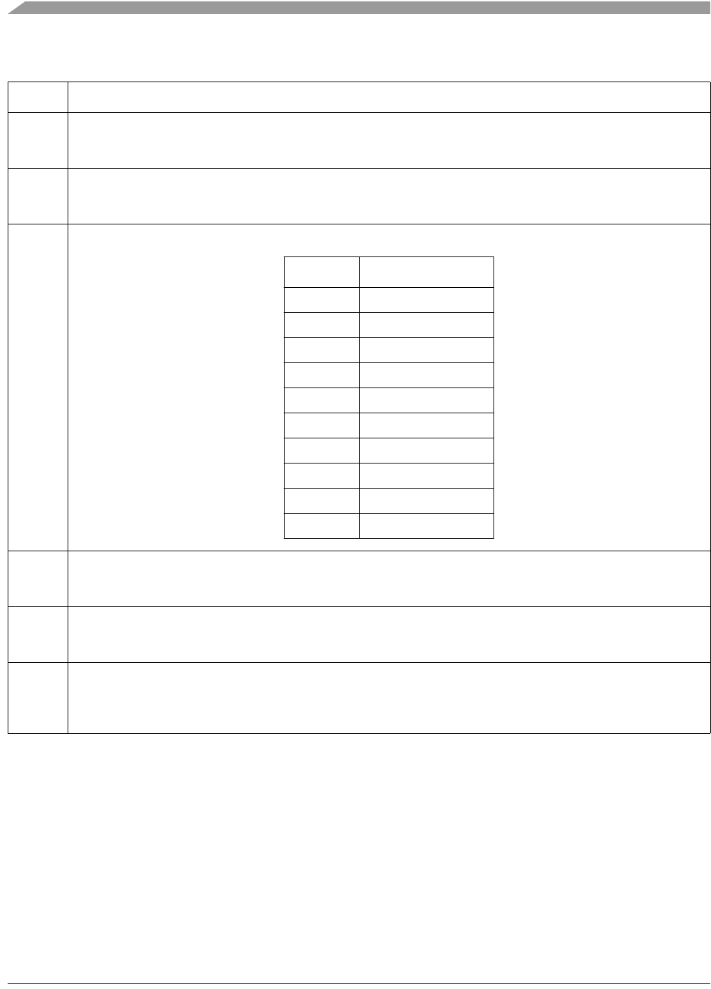
BITS
Transfer size. Determines the number of bits to be transferred for each entry in the queue.
9
CPOL
Clock polarity. Defines the clock polarity of QSPI_CLK.
0 The inactive state value of QSPI_CLK is logic level 0.
1 The inactive state value of QSPI_CLK is logic level 1.
8
CPHA
Clock phase. Defines the QSPI_CLK clock-phase.
0 Data captured on the leading edge of QSPI_CLK and changed on the following edge of QSPI_CLK.
1 Data changed on the leading edge of QSPI_CLK and captured on the following edge of QSPI_CLK.
7–0
BAUD
Baud rate divider. The baud rate is selected by writing a value in the range 2–255. A value of zero disables the QSPI.
A value of 1 is an invalid setting. The desired QSPI_CLK baud rate is related to the internal bus clock and
QMR[BAUD] by the following expression:
QMR[BAUD] = f
sys/
/(2×[desired QSPI_CLK baud rate])
BITS Bits per Transfer
0000 16
0001–0111 Reserved
1000 8
1001 9
1010 10
1011 11
1100 12
1101 13
1110 14
1111 15