


Pulse-Width Modulation (PWM) Module
MCF52211 ColdFire® Integrated Microcontroller Reference Manual, Rev. 2
27-10 Freescale Semiconductor
(PWMEn=0), the PWMCNTn register does not count. When a channel is enabled (PWMEn=1), the
associated PWM counter starts at the count in the PWMCNTn register. For more detailed information on
the operation of the counters, refer to Section 27.3.2.4, “PWM Timer Counters.”
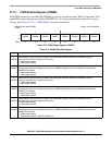
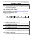
27.2.10 PWM Channel Period Registers (PWMPERn)
The PWM period registers determine the period of the associated PWM channel. Refer to Section 27.3.2.3,
“PWM Period and Duty” for more information.
Calculating the output period depends on the output mode (center-aligned has twice the period as
left-aligned mode) as well as PWMPERn. See the below equation:
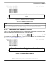
Eqn. 27-3
For boundary case programming values (e.g. PWMPERn = 0x00), please refer to Section 27.3.2.8, “PWM
Boundary Cases”.
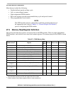
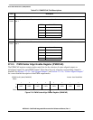
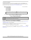
IPSBAR
Offset:
0x1B_000C (PWMCNT0)
0x1B_000D (PWMCNT1)
0x1B_000E (PWMCNT2)
0x1B_000F (PWMCNT3)
0x1B_0010 (PWMCNT4)
0x1B_0011 (PWMCNT5)
0x1B_0012 (PWMCNT6)
0x1B_0013 (PWMCNT7)
Access: User Read/Write
76543210
R
COUNT
W
Reset:00000000
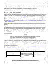
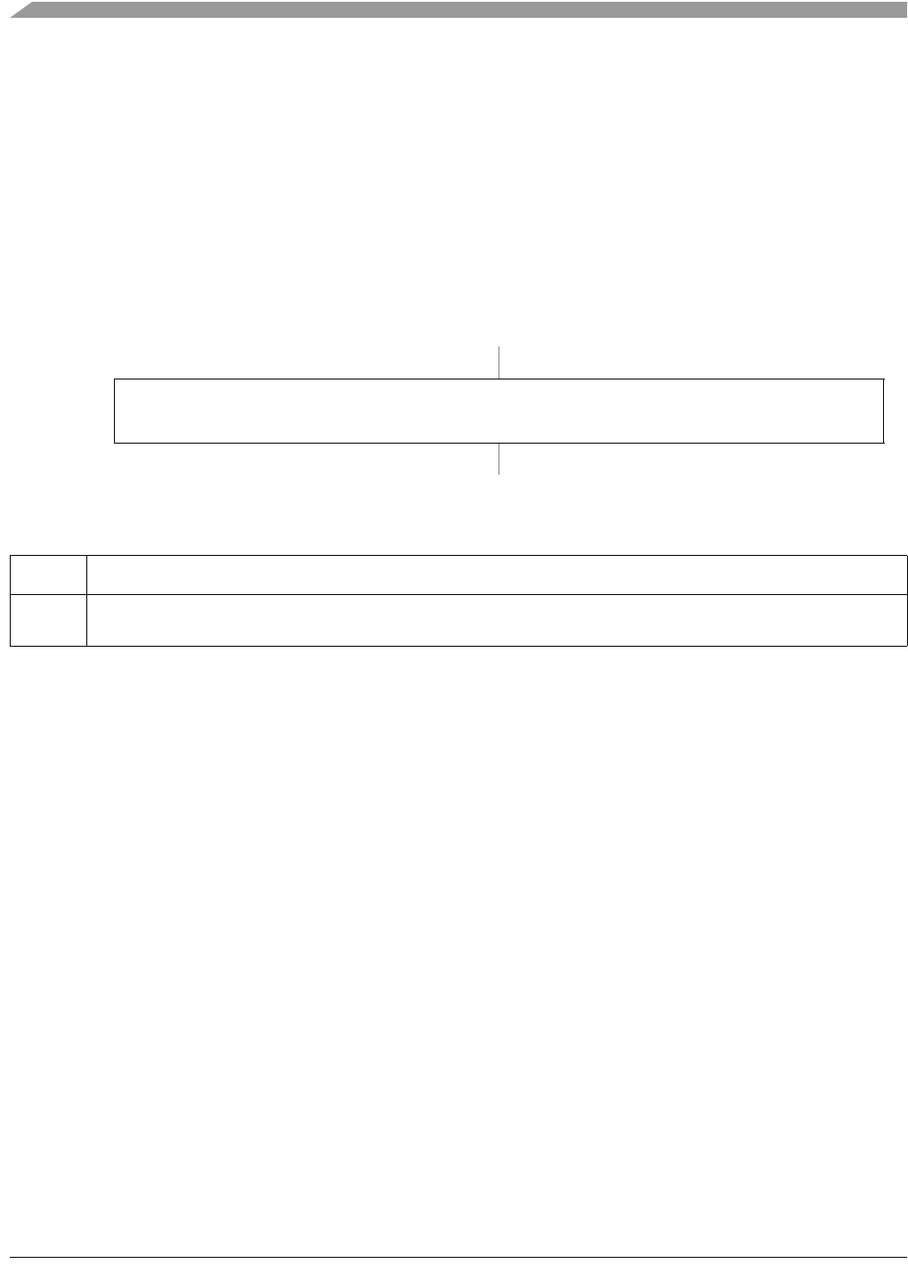
Figure 27-10. PWM Counter Registers (PWMCNTn)
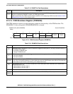
Table 27-10. PWMCNTn Field Descriptions
Field Description
7–0
COUNT
Current value of the PWM up counter. Resets to zero when written.
PWMn period Channel clock period PWMCAE CAEn[]1+()PWMPERn××=