


Analog-to-Digital Converter (ADC)
MCF52211 ColdFire® Integrated Microcontroller Reference Manual, Rev. 2
Freescale Semiconductor 26-37
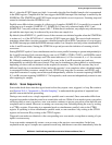
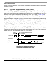
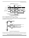
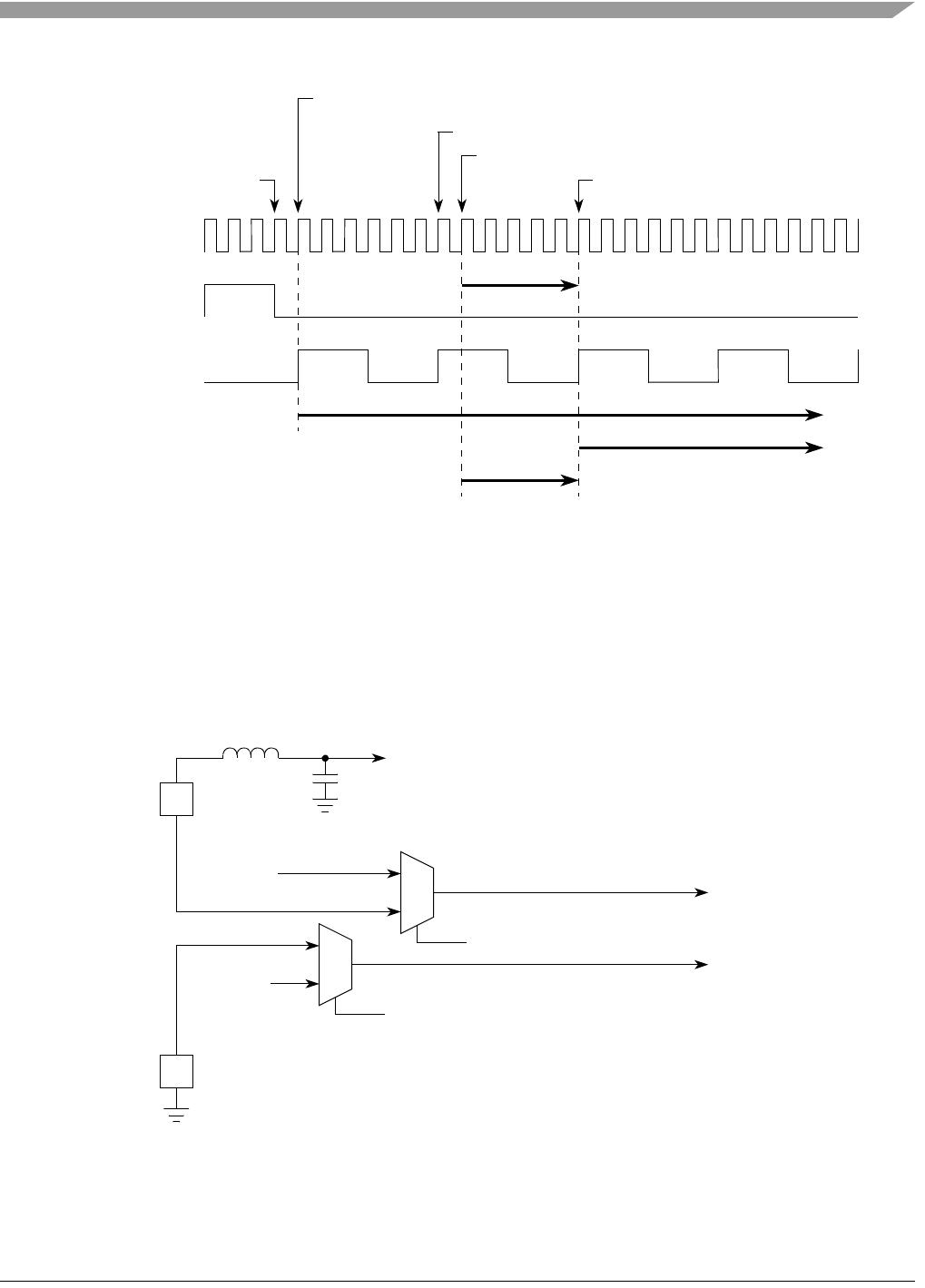
Figure 26-27. ADC Clock Resynchronization for
Non-Simultaneous Parallel Modes
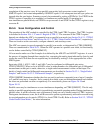
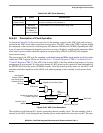
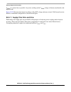
26.5.10 Voltage Reference Pins V
REFH
and V
REFL
The voltage difference between V
REFH
and V
REFL
provides the reference voltage that all analog inputs are
measured against. The reference voltage should be provided from a low noise filtered source capable of
providing up to 1mA of reference current.
Figure 26-28. ADC Voltage Reference Circuit
When tying V
REFH
to the same potential as V
DDA,
relative measurements are being made with respect to
the amplitude of V
DDA
. It is imperative that special precautions be taken to assure the voltage applied to
START0
Asserted
System Clock
Old ADC Clock
ADC Clock After
Resynchronization
ADCA Scan
ADCB Scan
ADCB Scan Start
ADCB Scan Should Start Here
START1 Asserted
ADC Conversion Clock Resynchronized
ADCA Scan Start
Delay in start because ADC Clock cannot
be resynchronized: 5 System Clocks
Wait for next rising
edge of ADC
Conversion Clock
V
REFH
External
Reference
Voltage
0.1µF
V
REFL
1.0mH
V
RL
SEL_VREFL
V
REFH
to ADC
V
REFL
to ADC
SEL_VREFH
V
RH