


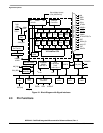
Signal Descriptions
MCF52211 ColdFire® Integrated Microcontroller Reference Manual, Rev. 2
2-10 Freescale Semiconductor
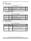
2.9 I
2
C I/O Signals
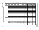
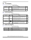
Table 2-8 describes the I
2
C serial interface module signals.
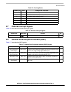
2.10 UART Module Signals
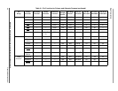
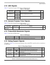
Table 2-9 describes the UART module signals.
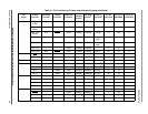
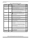
2.11 DMA Timer Signals
Table 2-10 describes the signals of the four DMA timer modules.
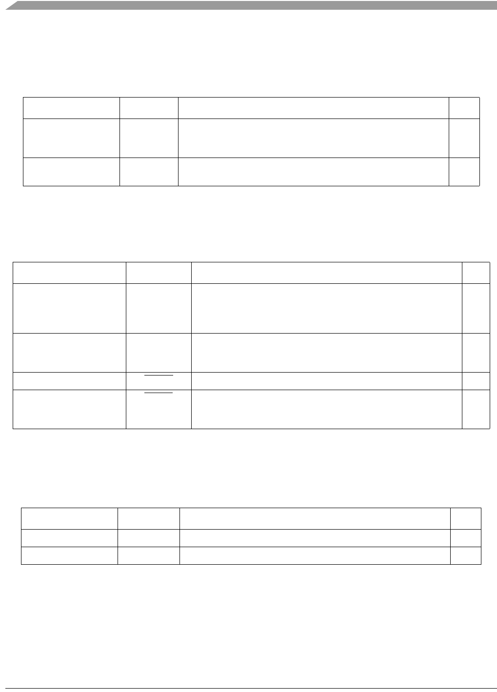
Table 2-8. I
2
C I/O Signals
Signal Name Abbreviation Function I/O
Serial Clock SCLn Open-drain clock signal for the for the I
2
C interface. It is driven by the
I
2
C module when the bus is in master mode or it becomes the clock
input when the I
2
C is in slave mode.
I/O
Serial Data SDAn Open-drain signal that serves as the data input/output for the I
2
C
interface.
I/O
Table 2-9. UART Module Signals
Signal Name Abbreviation Function I/O
Transmit Serial Data Output UTXDn Transmitter serial data outputs for the UART modules. The output is
held high (mark condition) when the transmitter is disabled, idle, or in
the local loopback mode. Data is shifted out, LSB first, on this pin at
the falling edge of the serial clock source.
O
Receive Serial Data Input URXDn Receiver serial data inputs for the UART modules. Data is received on
this pin LSB first. When the UART clock is stopped for power-down
mode, any transition on this pin restarts it.
I
Clear-to-Send UCTS
n Indicate to the UART modules that they can begin data transmission. I
Request-to-Send URTSn Automatic request-to-send outputs from the UART modules. This
signal can also be configured to be asserted and negated as a
function of the RxFIFO level.
O
Table 2-10. DMA Timer Signals
Signal Name Abbreviation Function I/O
DMA Timer Input DTINn Event input to the DMA timer modules. I
DMA Timer Output DTOUTn Programmable output from the DMA timer modules. O