


Analog-to-Digital Converter (ADC)
MCF52211 ColdFire® Integrated Microcontroller Reference Manual, Rev. 2
26-6 Freescale Semiconductor
26.4.2.2 CTRL2 Under Parallel Scan Modes
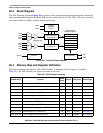
When the ADC operates in a parallel scan mode, the CTRL2 register is used to control the operation of
converter B. The interaction between converters A and B (and hence CTRL1 and CTRL2) is determined
by the CTRL2[SIMULT] bit. By default, CTRL2[SIMULT] equals 1 and converter B operates together
with converter A. In this case, the STOP1, START1, SYNC1, and EOSIE1 bits in the CTRL2 register do
not affect converter B operation. If CTRL2[SIMULT] equals 0, these bits and the SYNC1 input are used
to control the converter B scan. In this case, EOSIE1 enables the EOSI1 interrupt, signaling the end of a
B converter scan. In addition, ADSTAT[CIP1] is used to indicate a converter B scan is active.
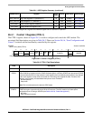
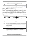
Table 26-3. CTRL2 Field Descriptions Under Sequential Scan Modes
Field Description
15–5 Reserved, should be cleared.
4–0
DIV
Clock Divisor Select. This field controls the divider circuit, which generates the ADC clock by dividing the
system clock by 2×DIV+1. DIV must be chosen so the ADC clock does not exceed 5.0 MHz. See Ta ble 26- 5
for a listing of ADC clock frequency based on the value of DIV for several configurations.
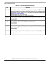
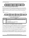
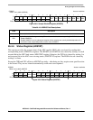
IPSBAR
Offset: 0x19_0002 (CTRL2)
Access: read/write
15 14 13 12 11 10 9 8 7 6 5 4 3 2 1 0
R 0
STOP1 SYNC1 EOSIE1
00000
SIMU
LT
DIV
W
START1
Reset 0 1 0 1 0 0 0 0 0 0 0 0 0 0 1 0
Figure 26-4. Control 2 Register (CTRL2) Under Parallel Scan Modes
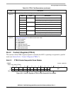
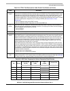
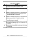
Table 26-4. CTRL2 Field Descriptions Under Parallel Scan Modes
Field Description
15 Reserved, should be cleared.
14
STOP1
Stop Conversion 1bit. In parallel-scan modes when SIMULT equaling 0, setting STOP1 stops parallel scans
in the B converter and prevents new scans from starting. Any further SYNC1 input pulses (see the SYNC1
field description) or writes to START1 are ignored until STOP1 is cleared. After the ADC is in stop mode, the
result registers can be modified by the processor. Any changes to the result registers in stop mode are
treated as if the analog core supplied the data. Therefore, limit checking, zero crossing, and associated
interrupts can occur if enabled.
0 Normal operation
1 Stop mode
Note: This is not the same as the device’s STOP mode.
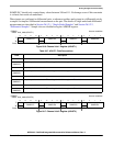
13
START1
Start Conversion 1 bit. In parallel-scan modes when SIMULT equaling 0, a scan by the B converter is started
by writing a 1 to this bit. START1 is write-only. Writing 1 to the START1 bit again is ignored until the end of
the current scan. The ADC must be in a stable power configuration prior to writing to START1 (see
Section 26.5.8, “Power Management”).
0 No action
1 Start command is issued