


Universal Serial Bus, OTG Capable Controller
MCF52211 ColdFire® Integrated Microcontroller Reference Manual, Rev. 2
15-16 Freescale Semiconductor
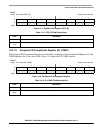
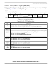
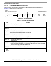
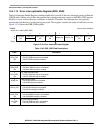
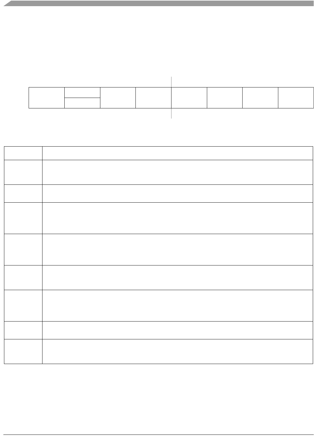
15.4.1.8 OTG Control Register (OTG_CTRL)
The OTG Control Register controls the operation of VBUS and Data Line termination resistors.
Figure 15-14 shows the OTG_CTRL register.
IPSBAR
Offset:
0x1C_001C (OTG_CTRL) Access: User read/write
76543210
R
DP_HIGH
RSVD
DP_LOW DM_LOW VBUS_ON OTG_EN
VBUS_
CHG
VBUS_
DSCHG
W
Reset:00000000
Figure 15-14. OTG Control Register
Table 15-18. OTG_CTRL Field Descriptions
Field Description
7
DP_HIGH
D+ Data Line pull-up resistor enable
0 D+ pull-up resistor is not enabled
1 D+ pull-up resistor is enabled
6
Reserved
Reserved, should read zero.
5
DP_LOW
D+ Data Line pull-down resistor enable
0 D+ pull-down resistor is not enabled
1 D+ pull-down resistor is enabled
This bit should always be enabled together with bit 4 (DM_LOW)
4
DM_LOW
D- Data Line pull-down resistor enable
0 D- pull-down resistor is not enabled
1 D- pull-down resistor is enabled
This bit should always be enabled together with bit 5 (DP_LOW)
3
VBUS_ON
VBUS power signal control
0 The VBUS power signal is not on
1 VBUS power is on
2
OTG_EN
On-The-Go pull-up/pull-down resistor enable
0 If USB_EN is set and HOST_MODE is clear in the Control Register (CTL), then the D+ Data Line pull-up
resistors are enabled. If HOST_MODE is set the D+ and D- Data Line pull-down resistors are engaged.
1 The pull-up and pull-down controls in this register are used
1
VBUS_CHG
When this bit is set, the VBUS signal is charged through a resistor
0
VBUS
_DSCHG
When this bit is set, the VBUS signal is discharged through a resistor.