


Pulse-Width Modulation (PWM) Module
MCF52211 ColdFire® Integrated Microcontroller Reference Manual, Rev. 2
27-12 Freescale Semiconductor
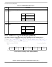
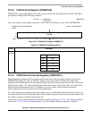
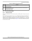
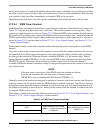
27.2.12 PWM Shutdown Register (PWMSDN)
The PWM shutdown register provides emergency shutdown functionality of the PWM module. The
PWMSDN[7:1] bits are ignored if PWMSDN[SDNEN] is cleared.
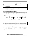
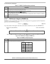
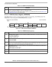
Table 27-12. PWMDTYn Field Descriptions
Field Description
7–0
DUTY
Contains the duty value used to determine when a transition occurs on the PWM output signal. When a match occurs
with the corresponding PWMCNTn register, the PWM output toggles.
If DUTY equals 0x00, the PWMn output is always low (PPOLn=1) or always high (PPOLn=0). See Section 27.3.2.8,
“PWM Boundary Cases” for other special cases.
IPSBAR
Offset:
0x1B_0024 (PWMSDN) Access: Read/Write
76543210
R IF
IE
0
LVL
0 PWM7IN
PWM7IL SDNEN
W w1c RESTART
Reset:00000000
Figure 27-13. PWM Shutdown Register (PWMSDN)
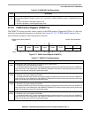
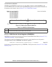
Table 27-13. PWMSDN Field Descriptions
Field Description
7
IF
PWM interrupt flag. Any change in state of PWM7IN is flagged by setting this bit. The flag is cleared by writing a 1
to it. Writing 0 has no effect.
0 No change in PWM7IN input
1 Change in PWM7IN input
6
IE
PWM interrupt enable. An interrupt is triggered to the device’s interrupt controller when PWMSDN[IF] is set.
0 Interrupt is disabled
1 Interrupt is enabled
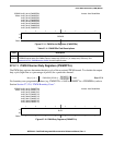
5
RESTART
PWM restart. After setting the RESTART bit, the PWM channels start running after the corresponding counter resets
to zero. Also, if emergency shutdown is cleared (after being set), the PWM outputs restart after the corresponding
counter resets to zero. This bit is self-clearing, so is always read as zero.
4
LVL
PWM shutdown output level. Describes the behavior of the PWM outputs when PWM7IN input is asserted and
PWMSDN[SDNEN] is set.
0 PWM outputs are forced to logic 0
1 PWM outputs are forced to logic 1
3 Reserved, should be cleared.
2
PWM7IN
PWM channel 7 input status. Reflects the current status of the PWMOUT7 pin. Read only.