


UART Modules
MCF52211 ColdFire® Integrated Microcontroller Reference Manual, Rev. 2
24-16 Freescale Semiconductor
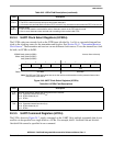
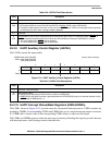
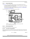
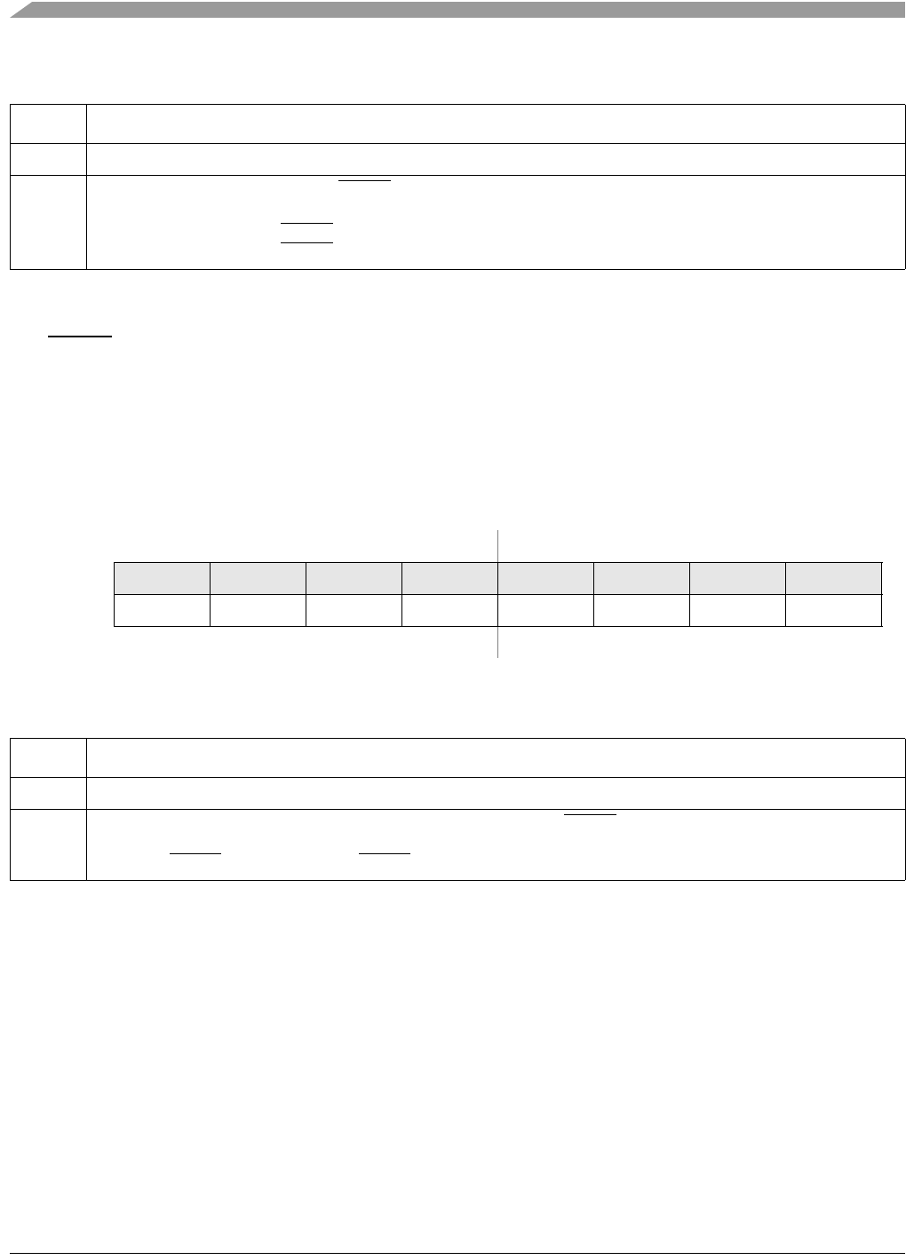
24.3.13 UART Output Port Command Registers (UOP1n/UOP0n)
The URTSn output can be asserted by writing a 1 to UOP1n[RTS] and negated by writing a 1 to
UOP0n[RTS]. See Figure 24-16.
24.4 Functional Description
This section describes operation of the clock source generator, transmitter, and receiver.
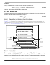
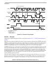
24.4.1 Transmitter/Receiver Clock Source
The internal bus clock serves as the basic timing reference for the clock source generator logic, which
consists of a clock generator and a programmable 16-bit divider dedicated to each UART. The 16-bit
divider is used to produce standard UART baud rates.
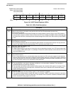
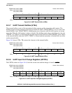
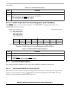
Table 24-11. UIPn Field Descriptions
Field Description
7–1 Reserved
0
CTS
Current state of clear-to-send. The UCTS
n value is latched and reflects the state of the input pin when UIPn is read.
Note: This bit has the same function and value as UIPCRn[RTS].
0 The current state of the UCTS
n input is logic 0.
1 The current state of the UCTSn input is logic 1.
IPSBAR
Offset:
0x00_0238 (UOP10)
0x00_023C (UOP00)
0x00_0278 (UOP11)
0x00_027C (UOP01)
0x00_02B8 (UOP12)
0x00_02BC (UOP02)
Access: User write-only
76543210
R
W 0 0 0 0 0 0 0 RTS
Reset:00000000
Figure 24-16. UART Output Port Command Registers (UOP1n/UOP0n)
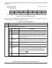
Table 24-12. UOP1n/UOP0n Field Descriptions
Field Description
7–1 Reserved, must be cleared.
0
RTS
Output port output. Controls assertion (UOP1)/negation (UOP0) of URTS
n output.
0 Not affected.
1 Asserts URTS
n in UOP1. Negates URTSn in UOP0.