


Clock Module
MCF52211 ColdFire® Integrated Microcontroller Reference Manual, Rev. 2
Freescale Semiconductor 6-17
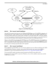
6.8 Functional Description
This section provides a functional description of the clock module.
6.8.1 System Clock Modes
The system clock source and PLL mode (enabled/disabled) are determined during reset (see Table 10-5).
The values of CLKMOD[1:0] (and XTAL if CLKMOD0 does not equal 1) are latched during reset and are
of no importance after reset is negated. If CLKMOD1 or CLKMOD0 change during a reset other than
power-on reset, the internal clocks may glitch as the system clock source is changed between external
clock mode and PLL clock mode. When CLKMOD1 or CLKMOD0 is changed in reset, an immediate
loss-of-lock condition occurs.
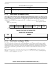
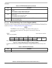
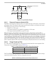
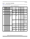
Table 6-16 shows the clock out frequency to clock in frequency relationships for the possible system clock
modes.
The external clock is divided by two internally to produce the system clocks.
6.8.2 Clock Operation During Reset
In external clock mode, the system is static and does not recognize reset until a clock is generated from the
reference clock source selected by the CLKMOD pins (see Section 6.6.4, “CLKMOD[1:0]).
1
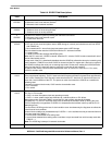
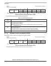
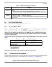
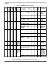
BWDSTOP
This bit determines whether the relaxation oscillator input to the BWT is stopped during Stop mode
operation.
0 The relaxation oscillator input to the BWT is stopped when the device enters Stop mode. When the
device leaves Stop mode, the relaxation oscillator input to the BWT is restored.
1 The relaxation oscillator input continues to be provided to the BWT when the device enters Stop mode.
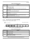
3
BWDSEL
BWT clock source selection bit. This bit determines the source of the BWT clock.
0 The source for the BWT is half the system frequency, f
sys/2
.
1 The source for the BWT is the relaxation oscillator. After this value is selected, CCLR[OSCSEL0] can no
longer be set.
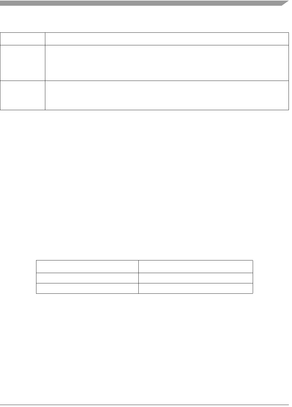
Table 6-16. Clock Out and Clock In Relationships
System Clock Mode PLL Options
1
1
f
ref
= input reference frequency
f
sys
= CLKOUT frequency
MFD ranges from 0 to 7.
RFD ranges from 0 to 7.
Normal PLL clock mode f
sys
= f
ref
× 2(MFD + 2)/2
RFD
External clock mode f
sys
= f
ref
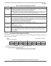
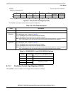
Table 6-15. BWCR Field Descriptions (continued)
Field Description