


Universal Serial Bus, OTG Capable Controller
MCF52211 ColdFire® Integrated Microcontroller Reference Manual, Rev. 2
15-4 Freescale Semiconductor
15.1.3 USB-FS Features
• USB 1.1 and 2.0 compliant full-speed device controller
• 16-Bidirectional end points
• DMA or FIFO data stream interfaces
• Low-power consumption
• On-The-Go protocol logic
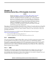
15.2 Functional Description
The USB-FS 2.0 full-speed/low-speed module communicates with the ColdFire processor core through status and
control registers, and data structures in memory.
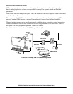
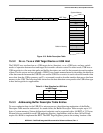
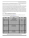
15.2.1 Data Structures
The function of the device operation is to transfer a request in the memory image to and from the Universal
Serial Bus. To efficiently manage USB endpoint communications the USB-FS implements a Buffer
Descriptor Table (BDT) in system memory. See Figure 15-3.
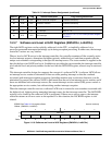
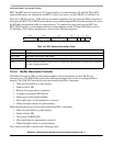
15.3 Programmers Interface
15.3.1 Buffer Descriptor Table
To efficiently manage USB endpoint communications the USB-FS implements a Buffer Descriptor Table
(BDT) in system memory. The BDT resides on a 512 byte boundary in system memory and is pointed to
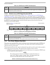
by the BDT Page Registers. Every endpoint direction requires two eight-byte Buffer Descriptor entries.
Therefore, a system with 16 fully bidirectional endpoints would require 512 bytes of system memory to
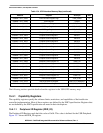
implement the BDT. The two Buffer Descriptor (BD) entries allows for an EVEN BD and ODD BD entry
for each endpoint direction. This allows the microprocessor to process one BD while the USB-FS is
processing the other BD. Double buffering BDs in this way allows the USB-FS to easily transfer data at
the maximum throughput provided by USB.
The software API intelligently manages buffers for the USB-FS by updating the BDT when needed. This
allows the USB-FS to efficiently manage data transmission and reception, while the microprocessor
performs communication overhead processing and other function dependent applications. Because the
buffers are shared between the microprocessor and the USB-FS a simple semaphore mechanism is used to
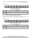
distinguish who is allowed to update the BDT and buffers in system memory. A semaphore bit, the OWN
bit, is cleared to 0 when the BD entry is owned by the microprocessor. The microprocessor is allowed read
and write access to the BD entry and the buffer in system memory when the OWN bit is 0. When the OWN
bit is set to 1, the BD entry and the buffer in system memory are owned by the USB-FS. The USB-FS now
has full read and write access and the microprocessor should not modify the BD or its corresponding data
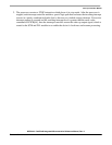
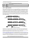
buffer. The BD also contains indirect address pointers to where the actual buffer resides in system memory.
This indirect address mechanism is shown in the following diagram.