


General Purpose Timer Module (GPT)
MCF52211 ColdFire® Integrated Microcontroller Reference Manual, Rev. 2
21-12 Freescale Semiconductor
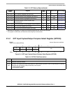
21.6.12 GPT Flag Register 1 (GPTFLG1)
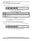
21.6.13 GPT Flag Register 2 (GPTFLG2)
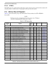
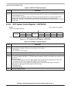
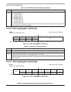
2–0
PR
Prescaler bits. Select the prescaler divisor for the GPT counter.
000 Prescaler divisor 1
001 Prescaler divisor 2
010 Prescaler divisor 4
011 Prescaler divisor 8
100 Prescaler divisor 16
101 Prescaler divisor 32
110 Prescaler divisor 64
111 Prescaler divisor 128
Note: The newly selected prescaled clock does not take effect until the next synchronized edge of the prescaled clock
when the clock count transitions to 0x0000.)
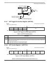
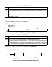
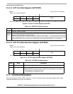
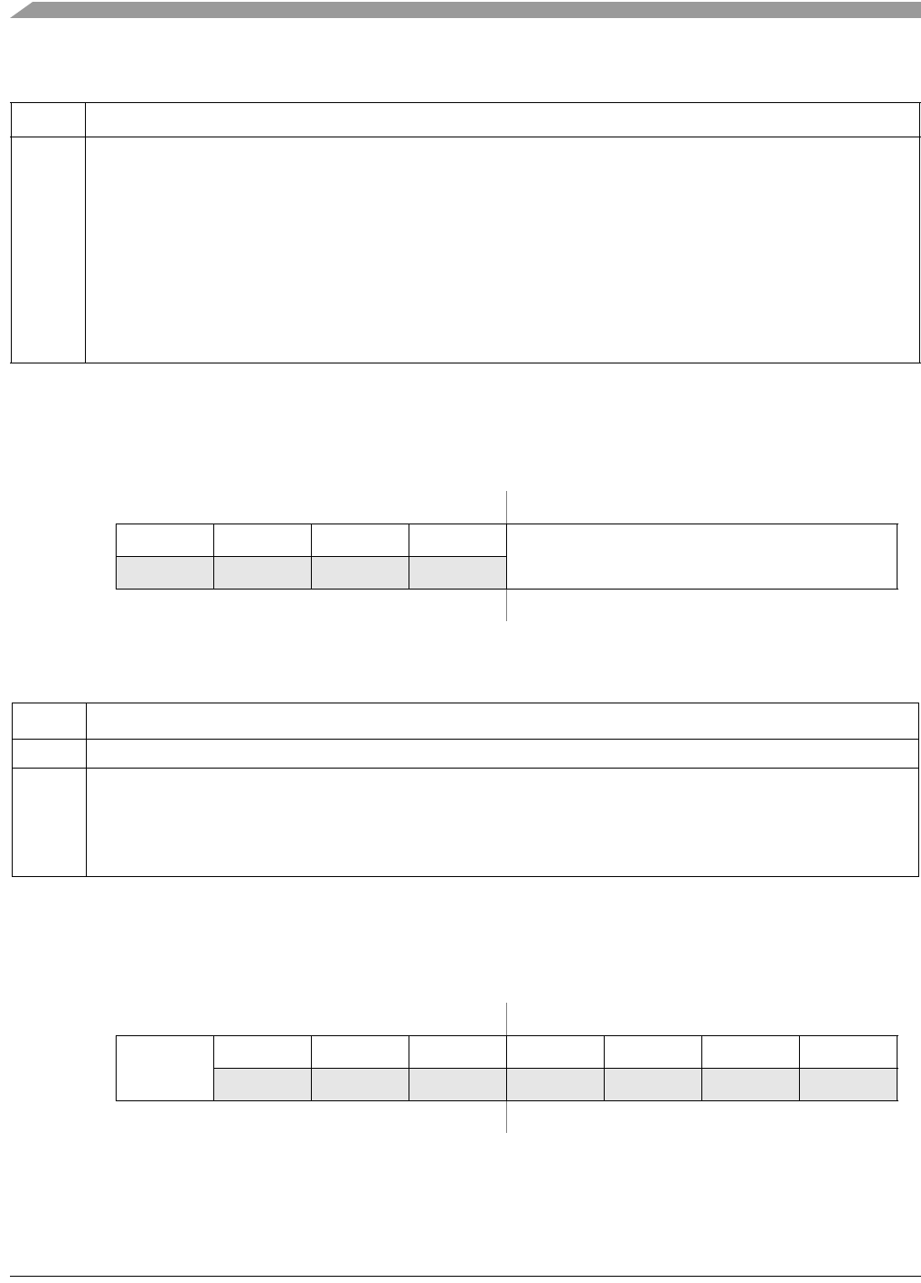
IPSBAR
Offset: 0x1A_000E (GPTFLG1)
Access: Supervisor read/write
76543210
R 0 0 0 0
CF
W
Reset:00000000
Figure 21-14. GPT Flag Register 1 (GPTFLG1)
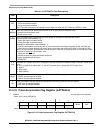
Table 21-15. GPTFLG1 Field Descriptions
Field Description
7–4 Reserved, should be cleared.
3–0
CnF
Channel flags. A channel flag is set when an input capture or output compare event occurs. These bits are read
anytime, write anytime (writing 1 clears the flag, writing 0 has no effect).
Note: When the fast flag clear all bit, GPTSCR1[TFFCA], is set, an input capture read or an output compare write
clears the corresponding channel flag. When a channel flag is set, it does not inhibit subsequent output compares
or input captures.
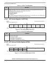
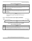
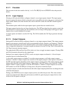
IPSBAR
Offset: 0x1A_000F (GPTFLG2)
Access: Supervisor read/write
76543210
R
TOF
0 0 00000
W
Reset:00000000
Figure 21-15. GPT Flag Register 2 (GPTFLG2)
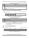
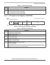
Table 21-14. GPTSCR2 Field Descriptions (continued)
Field Description