


Pulse-Width Modulation (PWM) Module
MCF52211 ColdFire® Integrated Microcontroller Reference Manual, Rev. 2
Freescale Semiconductor 27-7
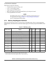
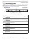
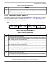
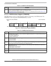
27.2.6 PWM Control Register (PWMCTL)
The PWMCTL register provides various control of the PWM module. Change the CONn(n+1) bits only
when both corresponding channels are disabled. See Section 27.3.2.7, “PWM 16-Bit Functions” for a
more detailed description of the concatenation function.
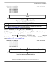
Table 27-6. PWMCAE Field Descriptions
Field Description
7–0
CAEn
Center align enable for channel n. The even-numbered channels’ center align enable has no effect when the
corresponding PWMCTL[CONn(n+1)] bit is set. For example, if PWMCTL[CON01] equals 1, PWMCAE[CAE0] has
no affect.
0 Channel n operates in left-aligned output mode
1 Channel n operates in center-aligned output mode
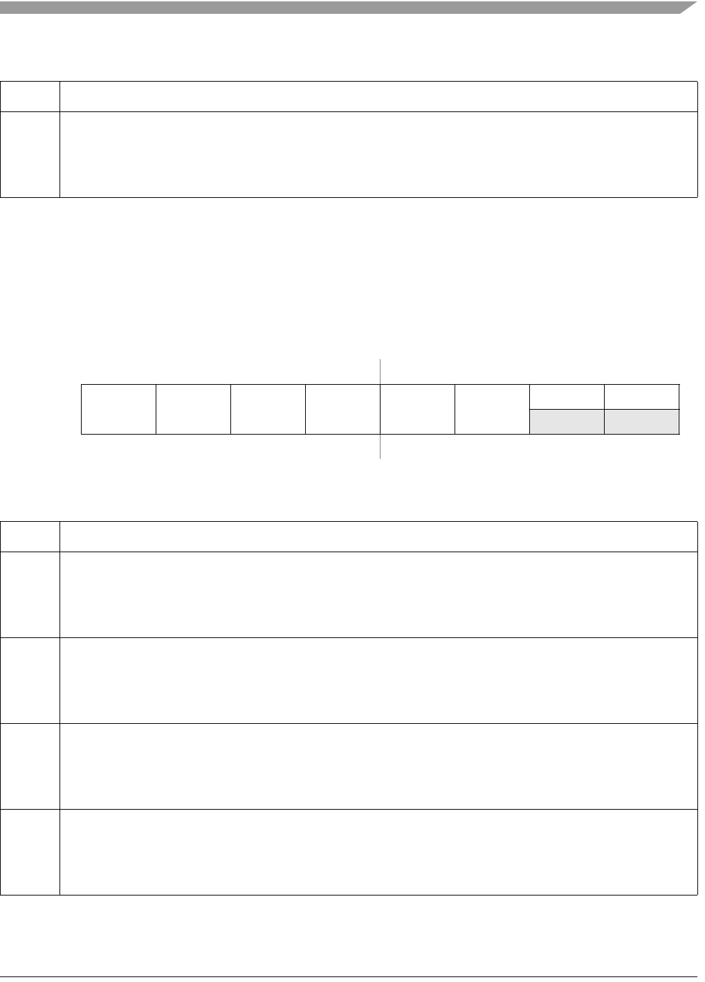
IPSBAR
Offset:
0x1B_0005 (PWMCTL) Access: User Read/Write
76543210
R
CON67 CON45 CON23 CON01 PSWAI PFRZ
0 0
W
Reset:00000000
Figure 27-7. PWM Control Register (PWMCTL)
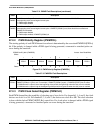
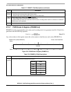
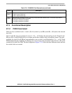
Table 27-7. PWMCTL Field Descriptions
Field Description
7
CON67
Concatenates PWM channels 6 and 7 to form one 16-bit PWM channel.
0 Channels 6 and 7 are separate 8-bit PWMs
1 Concatenate PWM 6 and 7. Channel 6 becomes the high order byte and channel 6 the low order byte. PWMOUT7
is the output for this 16-bit PWM signal, and PWMOUT6 is disabled. The channel 7 clock select, polarity, center align
enable, and enable bits control this concatenated output.
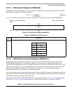
6
CON45
Concatenates PWM channels 4 and 5 to form one 16-bit PWM channel.
0 Channels 4 and 5 are separate 8-bit PWMs
1 Concatenate PWM 4 and 5. Channel 4 becomes the high order byte and channel 5 the low order byte. PWMOUT5
is the output for this 16-bit PWM signal, and PWMOUT4 is disabled. The channel 5 clock select, polarity, center align
enable, and enable bits control this concatenated output.
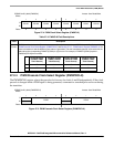
5
CON23
Concatenates PWM channels 2 and 3 to form one 16-bit PWM channel.
0 Channels 2 and 3 are separate 8-bit PWMs
1 Concatenate PWM 2 and 3. Channel 2 becomes the high order byte and channel 3 the low order byte. PWMOUT3
is the output for this 16-bit PWM signal, and PWMOUT2 is disabled. The channel 3 clock select, polarity, center align
enable, and enable bits control this concatenated output.
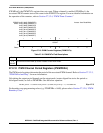
4
CON01
Concatenates PWM channels 0 and 1 to form one 16-bit PWM channel.
0 Channels 0 and 1 are separate 8-bit PWMs
1 Concatenate PWM 0 and 1. Channel 0 becomes the high order byte and channel 1 the low order byte. PWMOUT1
is the output for this 16-bit PWM signal, and PWMOUT0 is disabled. The channel 1 clock select, polarity, center align
enable, and enable bits control this concatenated output.