


System Control Module (SCM)
MCF52211 ColdFire® Integrated Microcontroller Reference Manual, Rev. 2
12-6 Freescale Semiconductor
• The back door enable bit, RAMBAR[BDE], is cleared at reset, disabling the module access to the
SRAM.
NOTE
The RAMBAR default value of 0x0000_0000 is invalid. The RAMBAR
located in the processor’s CPU space must be initialized with the valid bit
set before the CPU (or modules) can access the on-chip SRAM (see
Chapter 5, “Static RAM (SRAM),” for more information.
For details on the processor's view of the local SRAM memories, see Section 5.2.1, “SRAM Base Address
Register (RAMBAR).”
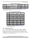
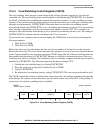
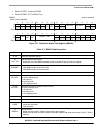
12.5.3 Core Reset Status Register (CRSR)
The CRSR contains a bit that indicates the reset source to the CPU. When the EXT bit (bit 7) reads as 1,
an external device driving RSTI has caused the most recent reset. The CRSR is updated by the control logic
when the reset is complete. Only one bit is set at any one time in the CRSR. The register reflects the cause
of the most recent reset. To clear a bit, a logic 1 must be written to the bit location; writing a zero has no
effect. Unused bits are reserved and should not be written.
NOTE
The reset status register (RSR) in the reset controller module provides
indication of all reset sources except the core watchdog timer (see
Chapter 10, “Reset Controller Module”).
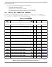
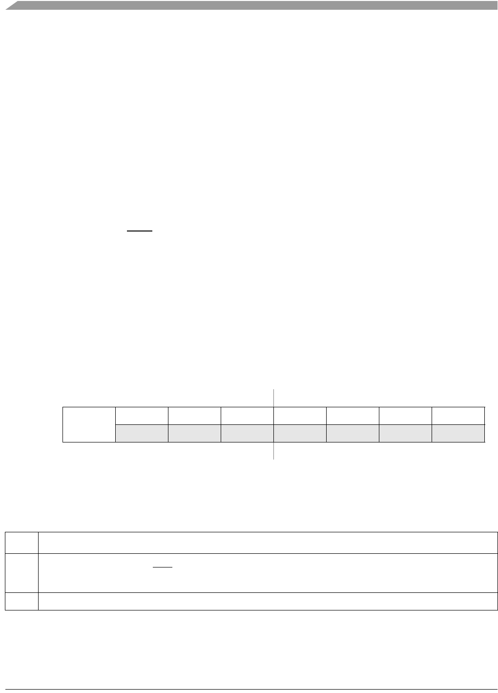
IPSBAR
Offset: 0x0010 (CRSR)
Access: read/write
76543210
R
EXT
0 0 00000
W
Reset:See Note0000000
Note: The reset value of EXT depend on the last reset source. All other bits are initialized to zero.
Figure 12-3. Core Reset Status Register (CRSR)
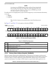
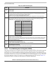
Table 12-5. CRSR Field Descriptions
Field Description
7
EXT
External reset.
1 An external device driving RSTI
caused the last reset. Assertion of reset by an external device causes the processor
core to initiate reset exception processing. All registers are forced to their initial state.
6–0 Reserved, should read as 0. Do not write to these locations.