134
CHAPTER 2 DEPENDENCE FUNCTIONS
■ Displaying and Setting External Probe Data
When a command that can use external probe data is executed, external probe data is displayed in 8-digit
binary or 2-digit hexadecimal format. The displayed bit order is in the order of the IC clip cable color code
order (Table 2.2-12). The MSB is at bit7 (Violet), and the LSB is at bit0 (Black). The bit represented by 1
means HIGH, while the bit represented by 0 means LOW. When data is input as command parameters, these
values are also used for input.
■ Commands for External Probe Data
Table 2.2-13 shows the commands that can be used to set or display external probe data.
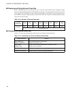
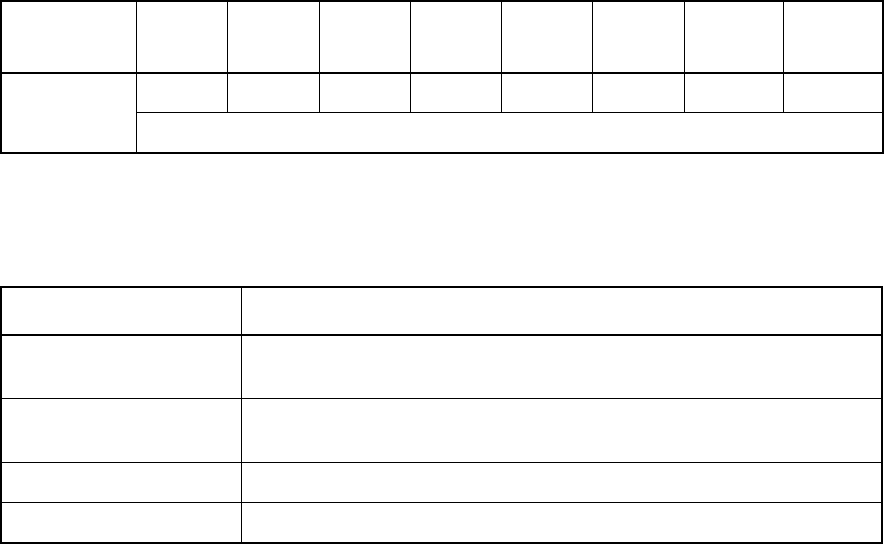
Table 2.2-12 Bit Order of External Probe Data
IC Clip
Cable Color
Violet Blue Green Yellow Orange Red Brown Black
Bit Order
Bit 7 Bit 6 Bit 5 Bit 4 Bit 3 Bit 2 Bit 1 Bit 0
External probe data
Table 2.2-13 Commands that can be used External Probe Data
Usable Command Function
SET SAMPLING
SHOW SAMPLING
Sets sampling timing for external probe
Samples external probe data
SET EVENT
SHOW EVENT
Enables to specify external probe data as condition for event
Displays event setup status
SHOW TRACE Displays external probe trace-sampled (single trace)
SHOW MULTITRACE Displays external probe trace-sampled (multi-trace)


