


167
CHAPTER 2 DEPENDENCE FUNCTIONS
2.3.6 Real-time Trace
While execution a program, the address, data and status information, and the data
sampled by an external probe can be sampled in machine cycle units and stored in the
trace buffer. This function is called real-time trace.
In-depth analysis of a program execution history can be performed using the data
recorded by real-time trace.
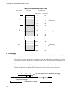
■ Trace Buffer
The data recorded by sampling in machine cycle units, is called a frame.
The trace buffer can store 64K frames (65536). Since the trace buffer has a ring structure, when it becomes
full, it automatically returns to the start to overwrite existing data.
■ Trace Data
Data sampled by the trace function is called trace data.
The following data is sampled:
• Address
•Data
• Status Information
- Access status: Read/Write/Internal access, etc.
- Device status: Instruction execution, Reset, Hold, etc.
- Queue status: Count of remaining bytes of instruction queue, etc.
- Data valid cycle information: Data valid/invalid
(Since the data signal is shared with other signals, it does not always output data. Therefore, the trace
samples information indicating whether or not the data is valid.)
• Execution time based on the previous trace frame (in 25-ns units)
■ Data Not Traced
The following data does not leave access data in the trace buffer.
- Portion of access data while in native mode.
When operating in the native mode, the F
2
MC-16L/16LX family of chips sometime performs
simultaneous multiple bus operations internally. However, in this emulator, monitoring of the internal
ROM bus takes precedence. Therefore, other bus data being accessed simultaneously may not be sampled
(in the debugging mode, all operations are sampled).
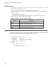
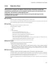
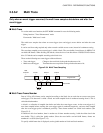
■ Frame number
A number is assigned to each frame of sampled trace data. This number is called a frame number.
The frame number is used to specify the display start position of the trace buffer. The value 0 is assigned to
trace data at the triggering position for sequencer termination. Negative values are assigned to trace data that
have been sampled before arrival at the triggering position (See Figure 2.3-2).
If there is no triggering position for sequencer termination, the value 0 is assigned to the last-sampled trace
data.