Servicing Motherboard Components 97
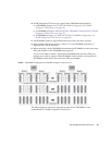
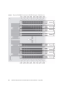
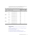
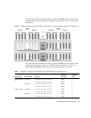
The following table identifies the order in which FB-DIMMS must be added when
upgrading the memory capacity of a SPARC Enterprise T5140 server.
Related Information
■ “FB-DIMM Configuration Guidelines for SPARC Enterprise T5240 Servers” on
page 98
■ “Identify Faulty FB-DIMMs Using the show faulty Command” on page 83
■ “Remove FB-DIMMs” on page 84
■ “Install Replacement FB-DIMMs” on page 86
■ “Verify Successful Replacement of Faulty FB-DIMMs” on page 88
■ “Upgrade Memory Configuration With Additional FB-DIMMs” on page 91
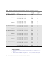
TABLE: FB-DIMM Configuration Installation Map (SPARC Enterprise T5140 Servers)
Branch Name Channel Name FRU Name
Motherboard FB-DIMM
Connector
FB-DIMM
Installation
Order
*
* Upgrade path: DIMMs should be added with each group populated in the order shown.
CMP 0,
Branch 0
Channel 0 /SYS/MB/CMP0/BR0/CH0/D0 J0500 1
/SYS/MB/CMP0/BR0/CH0/D1 J0600 2
Channel 1 /SYS/MB/CMP0/BR0/CH1/D0 J0700 1
/SYS/MB/CMP0/BR0/CH1/D1 J0800 2
CMP 0,
Branch 1
Channel 0 /SYS/MB/CMP0/BR1/CH0/D0 J0900 1
/SYS/MB/CMP0/BR1/CH0/D1 J1000 2
Channel 1 /SYS/MB/CMP0/BR1/CH1/D0 J1100 1
/SYS/MB/CMP0/BR1/CH1/D1 J1200 2
CMP 1,
Branch 0
Channel 0 /SYS/MB/CMP1/BR0/CH0/D0 J1800 1
/SYS/MB/CMP1/BR0/CH0/D1 J1900 3
Channel 1 /SYS/MB/CMP1/BR0/CH1/D0 J2000 1
/SYS/MB/CMP1/BR0/CH1/D1 J2100 3
CMP 1,
Branch 1
Channel 0 /SYS/MB/CMP1/BR1/CH0/D0 J2200 1
/SYS/MB/CMP1/BR1/CH0/D1 J2300 3
Channel 1 /SYS/MB/CMP1/BR1/CH1/D0 J2400 1
/SYS/MB/CMP1/BR1/CH1/D1 J2500 3


