


Servicing Customer-Replaceable Units 101
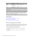
Use the following guidelines to spread the load evenly across CMP/memory
modules. If a slot is already populated with a device, install a new device in the next
available slot, in the order indicated.
Note – These are guidelines to spread out the I/O load across multiple
CMP/memory module pairs. These are not configuration restrictions.
External I/O Expansion Unit PCIe Link cards must be placed in a PCIe slot with a
CMP/memory module pair present as follows:
■ PCIe Slots 0 and 1 require CMP/Memory pair 0.
■ PCIe Slots 4 and 5 require CMP/Memory pair 1.
■ PCIe Slots 2 and 3 require CMP/Memory pair 2.
■ PCIe Slots 6 and 7 require CMP/Memory pair 3.
Related Information
■ “PCIe Device Identifiers” on page 99
■ “System Bus Topology” on page 167
■ “I/O Fabric in 2P Configuration” on page 168
■ “I/O Fabric in 4P Configuration” on page 169
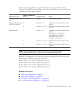
PCIe/XAUI Card Type
Number of CMP/Memory
Modules Installation Order Notes
10 GBit Ethernet (XAUI)
card
1, 2, 3 or 4 Slot 4, 5 Install XAUI cards first.
External I/O Expansion
Unit PCIe Link card
2 Slot 0, 4, 1, 5 Maximum of 4 cards; install in order
shown.
4 Slot 0, 4, 2, 6, 1, 5, 3, 7 Maximum of 8 cards; install in order
shown.
All other devices 1 Slot 0, 1, 2, 3 Maximum of 4 cards; install in order
shown.
PCIe Slots 4, 5, 6, and 7 are
unavailable in 1P systems.
Both XAUI Slots 0 and 1 are
available in 1P systems.
2 Slot 0, 4, 1, 5, 2, 6, 3, 7 Maximum of 8 cards; install in order
shown.
4 Slot 0, 4, 2, 6, 1, 5, 3, 7 Maximum of 8 cards; install in order
shown.